


ASUS A7V400-MX SEASUS A7V400-MX SE
ASUS A7V400-MX SEASUS A7V400-MX SE
ASUS A7V400-MX SE
1-231-23
1-231-23
1-23
5.5.
5.5.
5.
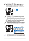
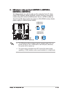
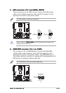
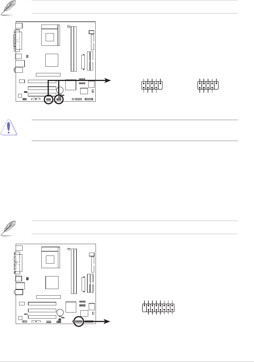
USB connectors (10-1 pin USB56, USB78)USB connectors (10-1 pin USB56, USB78)
USB connectors (10-1 pin USB56, USB78)USB connectors (10-1 pin USB56, USB78)
USB connectors (10-1 pin USB56, USB78)
These connectors are for USB 2.0 ports. Connect the USB module
cable to any of these connectors, then install the module to a slot
opening at the back of the system chassis.
The USB module is purchased separately.
A7V400-MX SE
A7V400-MX SE USB connectors
USB56
USB+5V
USB_P6-
USB_P6+
GND
NC
USB+5V
USB_P5-
USB_P5+
GND
1
USB78
USB+5V
USB_P8-
USB_P8+
GND
NC
USB+5V
USB_P7-
USB_P7+
GND
1
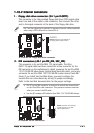
Never connect a
1394 cable1394 cable
1394 cable1394 cable
1394 cable to the USB connectors. Doing so will
damage the motherboard!
6.6.
6.6.
6.
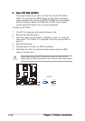
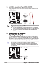
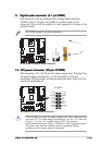
GAME/MIDI connector (16-1 pin GAME)GAME/MIDI connector (16-1 pin GAME)
GAME/MIDI connector (16-1 pin GAME)GAME/MIDI connector (16-1 pin GAME)
GAME/MIDI connector (16-1 pin GAME)
This connector is for a GAME/MIDI port. Connect the GAME/MIDI
module cable to this connector, then install the module to a slot
opening at the back of the system chassis. The GAME/MIDI port on
the module connects a joystick or a game pad for playing games, and
MIDI devices for playing or editing audio files.
The GAME/MIDI module is purchased separately.
A7V400-MX SE
A7V400-MX SE Game connector
GAME
+5V
+5V
J2B1
J2CX
MIDI_OUT
J2CY
J2B2
MIDI_IN
J1B1
J1CX
GND
GND
J1CY
J1B2
+5V