


1-241-24
1-241-24
1-24
Chapter 1: Product introductionChapter 1: Product introduction
Chapter 1: Product introductionChapter 1: Product introduction
Chapter 1: Product introduction
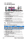
7.7.
7.7.
7.
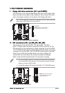
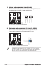
Internal audio connectors (4-pin CD, AUX)Internal audio connectors (4-pin CD, AUX)
Internal audio connectors (4-pin CD, AUX)Internal audio connectors (4-pin CD, AUX)
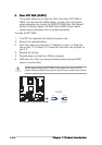
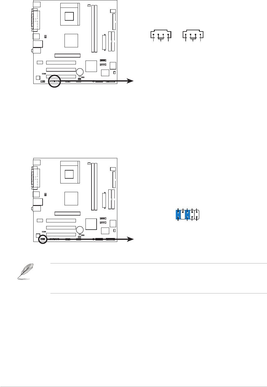
Internal audio connectors (4-pin CD, AUX)
These connectors allow you to receive stereo audio input from sound
sources such as a CD-ROM, TV tuner, or MPEG card.
A7V400-MX SE
A7V400-MX SE Internal audio connectors
CD(Black)AUX(White)
Right Audio Channel
Left Audio Channel
Ground
Right Audio Channel
Left Audio Channel
Ground
8.8.
8.8.
8.
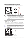
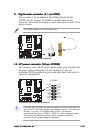
Front panel audio connectors (10-1 pin FP_AUDIO)Front panel audio connectors (10-1 pin FP_AUDIO)
Front panel audio connectors (10-1 pin FP_AUDIO)Front panel audio connectors (10-1 pin FP_AUDIO)
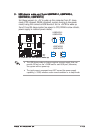
Front panel audio connectors (10-1 pin FP_AUDIO)
This connector is for the front panel audio daughterboard cable.
This connector supports the front panel audio I/O ports.
A7V400-MX SE
A7V400-MX SE Front panel audio connector
FP_AUDIO
BLINE_OUT_L
MIC2
Line out_R
Line out_L
BLINE_OUT_R
NC
MICPWR
+5VA
AGND
By default, the pins labeled LINE_OUT_R/BLINE_OUT_R and the pins
LINE_OUT_L/BLINE_OUT_L are shorted with jumper caps. Remove the
caps only when you are connecting the front panel audio cable.