


34 ASUS P2B-D2 User’s Manual
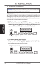
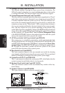
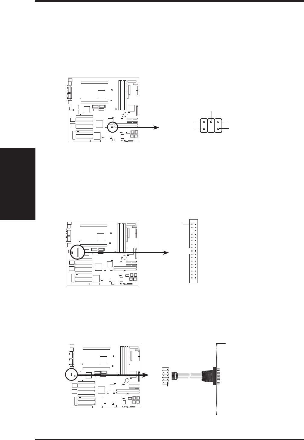
23. SB-Link™ Connector (6-1 pin SBLINK)
Using Intel’s PC-PCI and serialized IRQ protocols found in this motherboard’s
AGPset, this connector allows Sound Blaster 16 compatibility to AWE64D (Digi-
tal) or other PCI audio cards, enabling users to play Real-mode DOS games and
multimedia applications. SB-Link acts as a bridge between the motherboard and
the PCI audio card by providing the DMA and IRQ signals present in the ISA
bus but not available on the PCI bus.
NOTE: Pin 3 is removed to ensure the
correct orientation of the cable on it.
P2B-D2 SB-Link™ Connector
SBLINK
PC/PCI Request
Sideband Signal
5
6
1
DGND
2
DGND
Serial IRQ
PC/PCI Grant
Sideband Signal
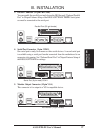
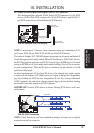
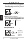
24. Floppy Disk Drive Connector (34-1pin FLOPPY)
This connector supports the provided floppy disk drive ribbon cable. After con-
necting the single end to the board, connect the two plugs on the other end to the
floppy drives. (Pin 5 is removed to prevent inserting in the wrong orienta-
tion when using ribbon cables with pin 5 plugged).
P2B-D2 Floppy Disk Drive Connector
NOTE: Orient the red stripe on
the floppy ribbon cable to Pin 1.
Pin 1
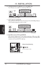
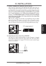
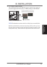
25. Serial Port Header (10-1 pin COM2)
The serial port bracket can be used to add an additional serial port for additional
serial devices.
P2B-D2 Serial (COM2) Port Connector
Orient the red stripe on the
serial ribbon cable to Pin 1
For the serial port connector
to be available, connect the
included serial cable set from
COM2 (25-pin male) to a free
expansion port.
TIP: You may also remove
the bracket connector and
mount them directly to the
case to save expansion
slot space.
COM 2
Pin 1
III. INSTALLATION
Connectors
III. INSTALLATION