


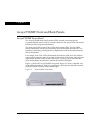


Chapter 3 Avaya P332MF Front and Back Panels
Avaya P332MF User’s Guide 9
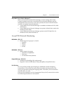
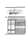
Figure 3.2 Avaya P332MF LEDs
Note: All LEDs are lit during a reset.
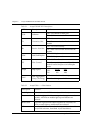
Table 3.1 Avaya P332MF LED Descriptions
LED Name Description LED Status
PWR Power status
OFF – power is off
ON – power is on
Blink – using BUPS only
OPR CPU operation
OFF – Module is booting
ON – Normal operation
SYS System Status
OFF – Module is a slave in a stack
ON – Module is the Master of the stack and
the Octaplane and Redundant cable are
connected correctly.
This LED will also light in Standalone mode.
Blink – Box is the stack Master and the stack
is in redundant mode.
The following Function LEDs apply to ports 1 to 66
LNK Port status
OFF – Port disabled
ON – Port enabled and link OK
Blink – Port enabled and the link is down
123
4
5
6
7
8
9
10 11 12
FC
Hspd
LAG
PWR
OPR
SYS
LNK COL Tx FDXRx
FIV
Function LEDs
Port LEDs
Left/Right
and Reset (both)
Switches
FIV Switch
EXPANSION
SLOT
51
52
53
54
55 56 57 58
59 60 61 62 63 64 65 66