


Chapter 4 Installation and Setup
24 Avaya P332MF User’s Guide
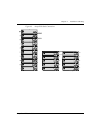
Installing Expansion Sub-modules
Caution: The expansion sub-modules contain components sensitive to electrostatic
discharge. Do not touch the circuit board unless instructed to do so.
Installing the Expansion Sub-module into the Avaya P330
1 Remove the blanking plate or other sub-module (if installed).
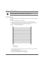
2 Insert the sub-module gently into the slot, ensuring that the Printed Circuit
Board (PCB) is aligned with the guide rails.
The PCB not the metal base plate fits into the guide rail.
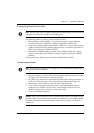
3 Firmly press the sub-module until it is completely inserted into the Avaya P330.
4 Gently tighten the two screws on the front panel of the expansion sub-module
by turning them.
Removing an Existing Expansion Sub-module
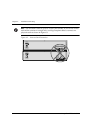
1 Loosen the screws by turning the knobs.
2 Take hold of the two knobs (one near each side of the front panel) and pull
gently but firmly towards yourself.
3 Insert another expansion sub-module or the blanking plate.
Note: If an expansion sub-module is removed from the stack with the power supply
on, all configuration definitions on expansion sub-modules are lost. To remove an
expansion sub-module and save configuration definitions:
1 Turn off the power supply.
2 Remove an expansion sub-module.
3 Insert another expansion sub-module.
4 Turn on the power supply.
Note: The Avaya P330 switch must not be operated with the expansion slot open;
the expansion sub-module slot should be covered with the supplied blanking plate
if necessary.