


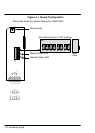

Hardware Setup 4-5
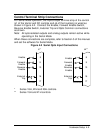
Control Terminal Strip Connections
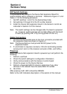
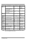
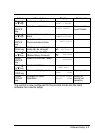
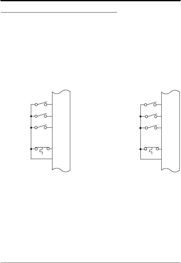
For Serial Mode operation, the Input/Output terminal strip of the control
(J1 of the Vector and DC controls and J4 of the Inverters) is wired as
shown in Figure 4-2. Connect the Enable, Forward Enable Switch,
Reverse Enable Switch, External Trip and Opto Common connections
as shown.
Note: All opto-isolated outputs and analog outputs remain active while
operating in the Serial Mode.
When these connections are complete, refer to Section 5 of this manual
and set the software for Serial Mode.
Figure 4-2 Serial Opto Input Connections
8
9
10
16
17
Common
J1*
8
9
10
16
17
Common
J4**
Enable
Forward
Enable
Reverse
Enable
External
Trip
Enable
Forward
Enable
Reverse
Enable
External
Trip
* Series 18H, 22H and 23H controls.
** Series 15H and 21H controls.