


Connections
Connections
7-2
5975288 BARCOGRAPHICS 8200 110497
5975288 BARCOGRAPHICS 8200 110497
7-2
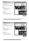
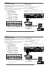
The projector has modular input facilities. The input slots can be filled
up with the following modules :
Video, S-video (PAL, SECAM, NTSC) input
order no. R9827900
RGBS/RGsB analog input
order no. : R9827910
RGB3S/RG3sB input
order no. : R9827920
Component Video input
order no. : R9827930
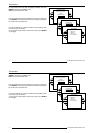
The sequence of insertion has no importance, exept when using a
RCVDS or VS05. It is even perfectly possible to insert several input
modules of one type.
Note : When using a RCVDS05 or VS05, the input configuration of the
projector must be as follows:
Slot 1 : video input module
Slot 2 : RGB analog input module
Slot 3 : Component input module
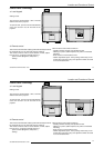
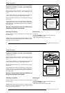
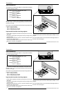
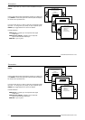
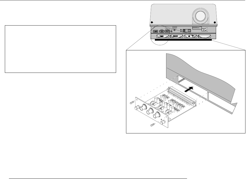
Input connections.
- Power down the projector and disconnect the power cord from the
wall outlet.
- Remove the dummy plate covering the chosen input slot by turning
out both screws.
- Slide the input module in the free slot. Insure the module is seated
correctly in the guide grooves.
- Press on both handles of the input module until the module plug
seats in the connector of the projector.
100 - 230 V
9 - 4 A
60 - 50 H z
RS232 OUT
0
I
IR- ACK NO WLE DG ED
IR-RECEI VED
DIAGNOS TICS
CODE
IR-RECEI VER
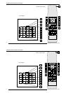
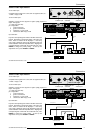
- Secure the input module by tightening both retaining screws.
- Reconnect the power cord to the wall outlet and switch on the
projector.
The new installed module can be selected with the digit buttons on
the RCU or the local keypad.
Input module insertion into the projector :
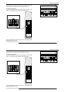
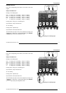
The projector has modular input facilities. The input slots can be filled
up with the following modules :
Video, S-video (PAL, SECAM, NTSC) input
order no. R9827900
RGBS/RGsB analog input
order no. : R9827910
RGB3S/RG3sB input
order no. : R9827920
Component Video input
order no. : R9827930
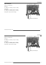
The sequence of insertion has no importance, exept when using a
RCVDS or VS05. It is even perfectly possible to insert several input
modules of one type.
Note : When using a RCVDS05 or VS05, the input configuration of the
projector must be as follows:
Slot 1 : video input module
Slot 2 : RGB analog input module
Slot 3 : Component input module
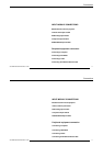
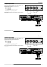
Input connections.
- Power down the projector and disconnect the power cord from the
wall outlet.
- Remove the dummy plate covering the chosen input slot by turning
out both screws.
- Slide the input module in the free slot. Insure the module is seated
correctly in the guide grooves.
- Press on both handles of the input module until the module plug
seats in the connector of the projector.
100 - 230 V
9 - 4 A
60 - 50 H z
RS232 OUT
0
I
IR- ACK NO WLE DG ED
IR-RECEI VED
DIAGNOS TICS
CODE
IR-RECEI VER
- Secure the input module by tightening both retaining screws.
- Reconnect the power cord to the wall outlet and switch on the
projector.
The new installed module can be selected with the digit buttons on
the RCU or the local keypad.
Input module insertion into the projector :