Random Access Adjustment Mode
5975288 BARCOGRAPHICS 8200 110497
11-7
Random Access Adjustment Mode
11-7
5975288 BARCOGRAPHICS 8200 110497
Options
Source number : The source number of a non-active source can be
changed to any other source number. This makes it possible to
create a file for future source numbers.
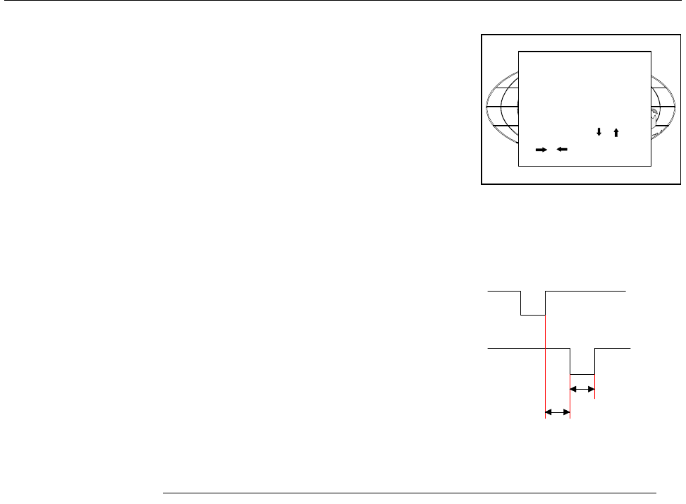
Clamp position : Clamping determines the black level of the signal.
The clamp pulse can be related to the leading or the trailing edge of
the sync pulse. Use the
ENTER
key to toggle between [leading] and
[trailing].
Clamp delay : The time between the leading edge of the clamp pulse
and the locked edge of the sync pulse.
Can be any value between 0 and 127. Change the value by pushing
the control disk to the left or to the right.
Clamp width : The width of the clamp pulse
Can be any value between 0 and 127. Change the value by pushing
the control disk to the left or to the right.
Field polarity : Default [auto]
[auto] = autodetection of the field polarity.
The field polarity function is used for interlaced images. Both rasters
of the image could be shifted in a wrong way (double lines are visilble
in the image). This can be corrected by forcing the field polarity to
[neg] or [pos].
Use the
ENTER
key to toggle between [auto], [pos] and [neg].
Field select : Default [both]
The field select is only used for interlaced images. One frame of an
interlaced image contains two fields, an even and an odd field. The
choice exists to project [both] fields on the screen or only the [even]
or [odd] field. This can be useful for 3D projection.
Use the
ENTER
key to toggle between [both], [even] and [odd].
Select with or
<ENTER> to toggle
or to change value
<EXIT> to return
Sync
pulse
Clamp
pulse
Clamp
delay
Clamp
width
trailing edge
leading edge
Example for clamp position [trailing]
EDIT FILE OPTIONS
Source number 1
Clamp position [leading]
Clamp delay 0
Clamp width 10
Field polarity [pos]
Field select [both]
Vertical refresh [sync]
Vert. sync polarity [leading]


