


724-746-5500 | blackbox.com
724-746-5500 | blackbox.com
Page 17
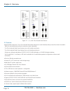
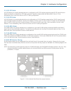
Chapter 2: Overview
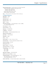
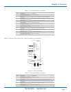
Table 2-1. 1-Port Serial Server components.
Number Component Description
1 (1) terminal block connector Used for DC power.
2 (1) Link LED Lights yellow for 10BASE-T or green for 100BASE-TX.
3 (1) Ready LED Flashes green when the unit is ready to transmit/receive data.
4 (1) Power LED Lights when power to the unit is on.
5 (1) Reset button Press to reset the unit.
6 (1) 2-position DIP switch Selects run or console mode.
7 (1) RJ-45 Ethernet connector Connects to Ethernet.
8 (1) RX LED Lights when data is being received.
9 (1) TX LED Lights when data is being transmitted.
10 (1) DB9 connector Connects to serial device.
11 (1) terminal block connector Links to serial device.
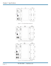
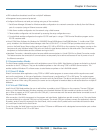
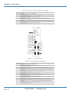
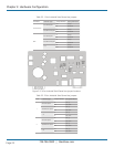
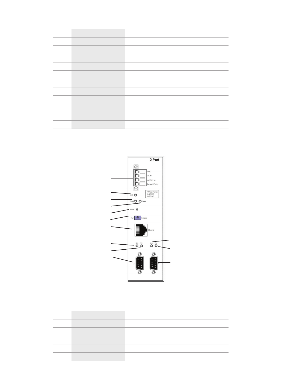
Figure 2-3 shows the 2-Port Serial Server. Table 2-2 describes its components.
1
2
3
4
5
6
7
8
9
10
8
9
10
Figure 2-3. 2-Port Serial Server.
Table 2-2. 2-Port Serial Server components.
Number Component Description
1 (1) terminal block connector Used for DC power.
2 (1) Link LED Lights yellow for 10BASE-T or green for 100BASE-TX.
3 (1) Ready LED Flashes green when the unit is ready to transmit/receive data.
4 (1) Power LED Lights when power to the unit is on.
5 (1) Reset button Press to reset the unit.