


724-746-5500 | blackbox.com
Page 58
724-746-5500 | blackbox.com
Appendix C: RS-485 Connections
Appendix C. RS-485 Connections
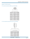
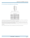
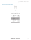
C.1 1-, 2-, or 4-Port Serial Server DB9 Pinout in RS-485H (Two-Wire, Half-Duplex) Mode
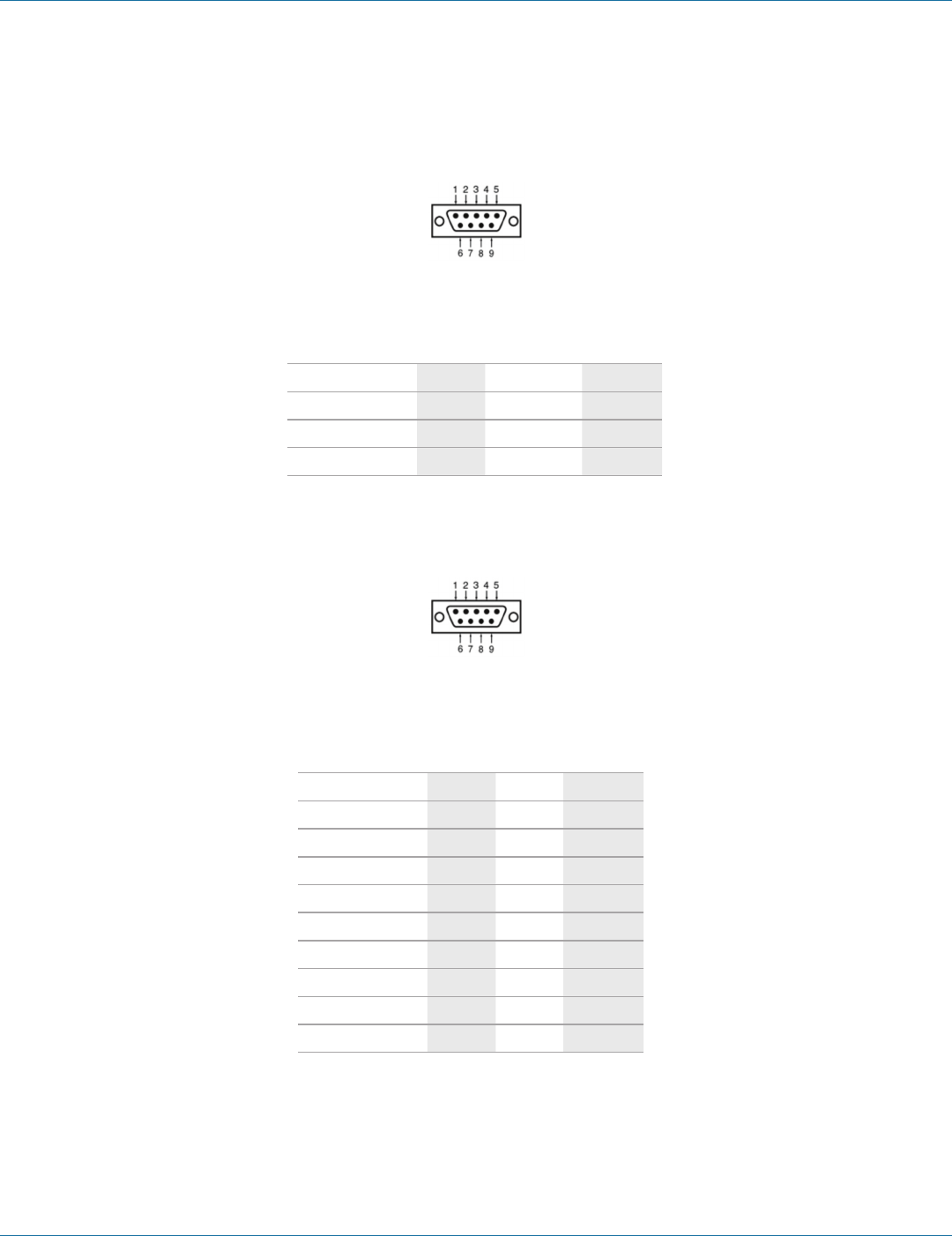
Figure C-1. DB9 male connector.
Table C-1. DB9 pinout in RS-485H mode.
RS-485 Signal Name Direction RS-485 DB9 M Pin
Data B (+) In/Out DATA B (+) 3
Data A (-) In/Out DATA A (-) 4
Signal Ground — GND 5
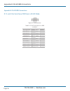
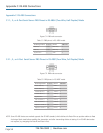
C.2 1-, 2-, or 4-Port Serial Server DB9 Pinout in RS-485F (Four-Wire, Full-Duplex) Mode
Figure C-2. DB9 male connector.
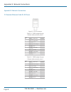
Table C-2. DB9 pinout in RS-485F mode.
RS-232 Signal Name Direction RS-422 DB9 M Pin
Receive Data A (-) In RXDA (-) 1
Receive Data B (+) In RXDB (+) 2
Transmit Data B (+) Out TXDB (+) 3
Transmit Data A (-) Out TXDA (-) 4
Signal Ground — GND 5
Clear To Send A (-) In CTSA (-) 6
Clear To Send B (+) In CTSB (+) 7
Request To Send B (+) Out RTSB (+) 8
Request To Send A (-) Out RTSA (-) 9
NOTE: Some RS-485 devices are marked opposite the RS-485 standard, which defines the Data B line as positive relative to Data
A during a Mark state before enabling the transmitter, and after transmitting before tri-stating. If an RS-485 device does
not respond, try swapping the Data B and Data A lines.