


8-/16-/24-Port 10/100 PoE PSE Web Smart Switch
724-746-5500 l www.blackbox.com
12
3. Installation
3.1 Hardware and Cable Installation
CAUTION: Wear a grounding device to avoid damage from electrostatic discharge. Be sure that the power switch is OFF
before you connect the power cord to the power source.
3.1.1 TP Port and Cable Installation
1. The switch’s TP port supports MDI/MDI-X auto-crossover, so you can use both types of cable, straight-through (Cable
pin-outs for RJ-45 jack 1, 2, 3, 6 to 1, 2, 3, 6 in 10/100M TP) and cross-over (Cable pin-outs for RJ-45 jack 1, 2, 3, 6 to
3, 6, 1, 2). Simply plug in the cable.
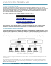
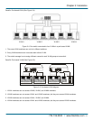
2. Connect one end of a CAT5 grade RJ-45 TP cable or above to a TP port on the switch and connect the other end to a
network-aware device such as a workstation or a server.
3. Repeat the above steps, as needed, for each RJ-45 port that you want to connect to a 10/100 TP device.
The switch is now ready to operate.
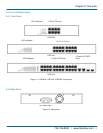
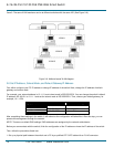
3.1.2 Installing an Optional SFP Transceiver Module
NOTE: If you do not plan to install SFP fiber transceivers in the LPB724A switch’s ports 25–26, skip this section.
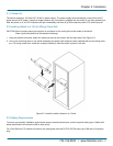
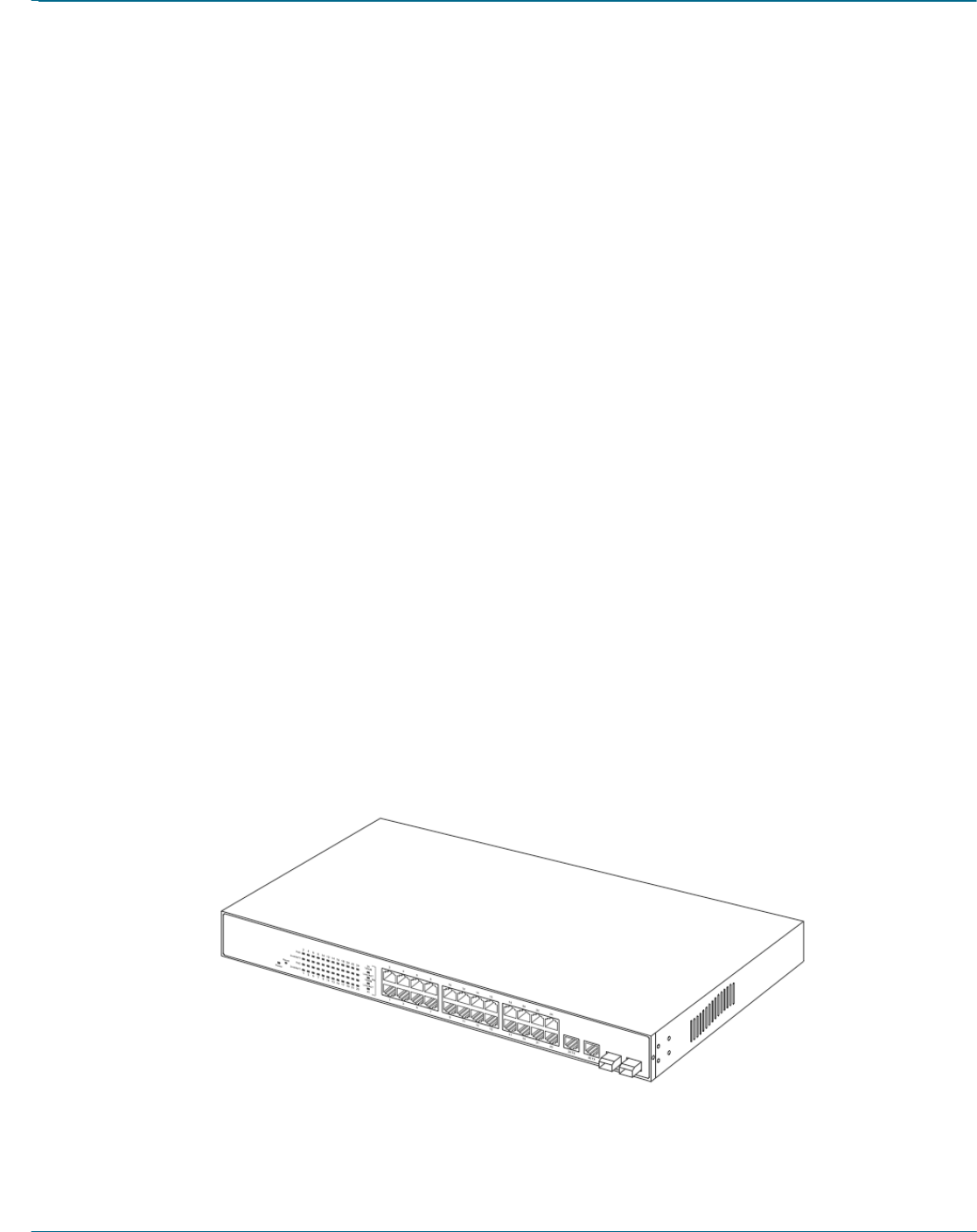
Slide the fiber transceiver module into one of the two open module slots in the switch as shown in Figure 3-1.
Connecting the SFP Module to the Chassis
The optional SFP modules are hot-swappable, so you can plug or unplug them before or after powering on the switch.
Verify that the SFP module is the right model and conforms to the chassis.
Slide the module into the slot. Make sure that the module is properly seated against the slot socket/connector.
Connect the fiber optic network cable to the connector(s) on the module.
If you want to install a second module in the switch, repeat steps 1–3.
Figure 3-1. Installing an SFP fiber transceiver into the LPB724A switch.
SFP transceiver module