


8-/16-/24-Port 10/100 PoE PSE Web Smart Switch
724-746-5500 l www.blackbox.com
14
3.4 Switch Cascading in Topology
Theoretically, the switch partitions the collision domain for each port in switch cascading so that you may uplink an
unlimited number of switches. In practice, the network extension (cascading levels and overall diameter) must comply with
the IEEE 802.3/802.3u and other 802.1 series protocol specifications, which limit the timing requirement from physical
signals defined by the Media Access Control (MAC) and PHY802.3 series specification, and the timer from some OSI
layer 2 protocols such as 802.1d, 802.1q, and LACP.
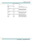
The TP cables, and devices’ bit-time (round-trip) delay are as described in Table 3-1.
100Base-TX TP
Round trip Delay: 512
Cat. 5 TP Wire:
1.12/m
TP to fiber Converter: 56
Bit Time unit: 0.01 s (1sec./100 Megabits)
Table 3-1. Cable’s bit-time (round-trip) delay.
Sum up all elements’ bit-time delay and the overall bit-time delay. They must be within Round Trip Delay (bit times)
requirements in a half-duplex network segment (collision domain). For full-duplex operation, this doesn’t apply.
3.5 Typical Network Topology in Deployment
A hierarchical network with minimum switch levels may reduce the timing delay between server and client station. This will
minimize the number of switches in any one path, lower the possibility of network loops, and improve network efficiency. If
more than two switches are connected in the same network, select one switch as Level 1 switch and connect all other
switches to it at Level 2. We recommend connecting the Server/Host to the Level 1 switch if no VLAN or other special
requirements are used.
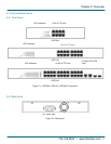
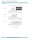
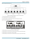
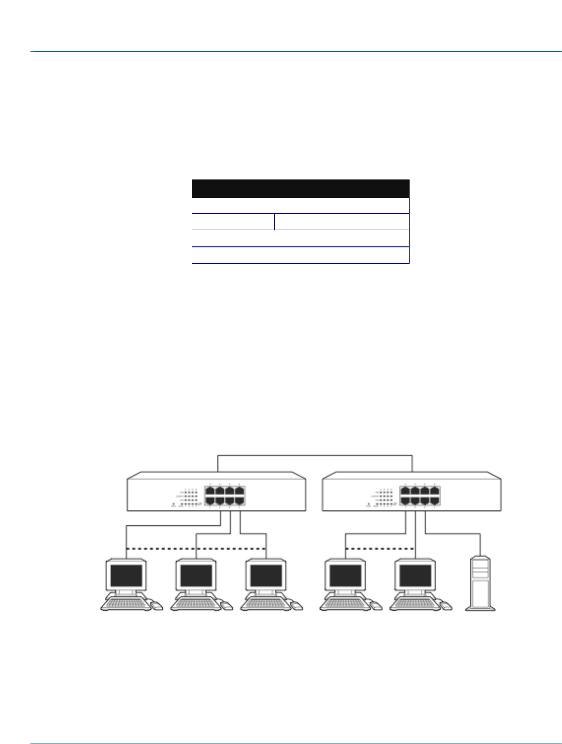
Case1: All switch ports are in the same local area network. Every port can access each other (See Figure 3-3).
Figure 3-3. No VLAN Configuration Diagram.
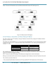
If VLAN is enabled and configured, each node in the network that can communicate each other directly is bound in the
same VLAN area.
Here VLAN area is defined by what VLAN you are using. The switch supports both port-based VLAN and tag-based
VLAN. They are different in practical deployment, especially in physical location. The following diagram shows how it
works and what the differences are.