


Chapter 4: Configuration
724-746-5500 | blackbox.com
Page 35
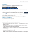
4.7.3 Transmitters > Configure Transmitter Page
When you click for a particular transmitter, this page lists information about the unit and allows numerous settings to be
configured.
4.7.3.1 IP Address
Allows you to alter the IP address of the transmitter unit. Any change in address will be enacted when you click the “Save”
button at the foot of the page. Any IP connections currently made to the transmitter will be ended.
4.7.3.2 Device Name, Description and Location
These are useful identifiers for the transmitter unit and its exact location. These become even more valuable as the number of
transmitters within the system increases.
4.7.3.3 Video Settings
This section allows you to directly adjust various key video controls within the transmitter in order to obtain the most efficient
operation taking into account connection speeds and the nature of the video images sent by that transmitter.
4.7.3.4 DDC
Allows you to use a global DDC setting, the monitor’s DDC or a particular DDC chosen from the list.
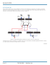
4.7.3.4.1 Background Refresh
The transmitter sends portions of the video image only when they change. To give the best user experience, the transmitter also
sends the whole video image, at a lower frame rate, in the background. The Background Refresh parameter controls the rate at
which this background image is sent. The default value is ‘every 32 frames’, meaning that a full frame is sent in the background
every 32 frames. Reducing this to ‘every 64 frames’ or more will reduce the amount of bandwidth that the transmitter consumes.
On a high-traffic network, this parameter should be reduced in this way to improve overall system performance. Options: Every 32
frames, Every 64 frames, Every 128 frames, Every 256 frames, or Disabled.
4.7.3.4.2 Color Depth
This parameter determines the number of bits required to define the color of every pixel. The maximum (and default) value is ‘24
bit’. By reducing the value you can significantly reduce bandwidth consumption, at the cost of video color reproduction. Options:
24 bit, 16 bit or 8 bit.
4.7.3.4.3 Peak Bandwidth Limiter
The transmitter will employ a ‘best effort’ strategy in sending video and other data over the IP network. This means it will use as
much of the available network bandwidth as necessary to achieve optimal data quality, although typically the transmitter will use
considerably less than the maximum available. To prevent the transmitter from ‘hogging’ too much of the network capacity, you
can reduce this setting to place a tighter limit on the maximum bandwidth permissible to the transmitter. Range: 1 to 100%.
4.7.3.4.4 Frame Skipping
Frame Skipping involves ‘missing out’ video frames between those captured by the transmitter. For video sources that update only
infrequently or for those that update very frequently but where high fidelity is not required, frame skipping is a good strategy for
reducing the overall bandwidth consumed by the system. Range: 0 to 100%.
4.7.3.5 Serial Settings
Serial Parity, Serial Data Bits, Serial Stop Bits, Serial Speed
This group of settings allows you to define the key parameters for the AUX port of the transmitter so that it matches the
operation of the device attached to it.
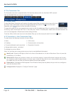
4.7.4 Transmitters > Update Firmware
Click this option to go straight to the Dashboard > Updates page. See Dashboard > Updates page for more details.