4-12
Confidential
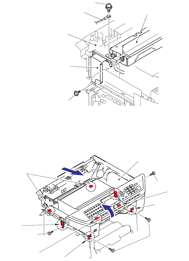
(24) Remove the cup S M3x6 SR Taptite screw, and remove the Screw pan (S/P washer)
M3.5x6 of the NCU FG harness ASSY.
Fig. 4-17
(25) Remove the four bind B M4x12 Taptite screws from the Joint cover.
(26) Release all Hooks of the Joint cover and lift up the front side of the Joint cover.
(27) Pull out the Joint cover to the front side.
Fig. 4-18
Screw, pan (S/P washer) M3.5X6
NCU FG harness ASSY
NCU unit
Joint cover ASSY
Driver PCB shield
Taptite cup S M3x6 SR
5
Taptite bind B M4x12
Taptite bind B M4x12
Taptite bind B M4x12
<Front side>
Hook
Hooks
Hook
Hook
Hook
Hook
Joint cover
27
26


