Chapter 3: LM Security Screens for 2H23-50R/2H33-37R Devices
3-12 Local Management Supplement
Network (Read-only)
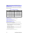
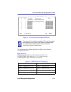
Indicates the network to which the port is currently attached. Table 3-5
shows the association between the connector (CONN) and Network on
the device.
Security State (Selectable)
Used to select the state of security for frames received by a specific port
on the connector. The states are as follows:
• NonSecure – Allows the ports on the connector to receive all frames.
The source address of received frames is not examined and the frames
are processed in a non secure state.
• LockOnNext – The next frame received by each port is examined to
learn its source address. After the source address of a frame is learned
on a port, it is now locked on that address and only those frames
received with that same source address are allowed on that port. All
frames received that do not have that same source address will cause
the device to execute the actions selected in the Action On Intruder
field.
• LockedOnAddr – The device locks down on the address that is
currently configured in the Port Level Security Configuration screen
(if one is entered) or on the source address of the currently received
frame. If an address was not configured or received, the device defaults
to the locked on address of “00-00-00-00-00-00” as indicated by
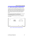
“XX-XX-XX-XX-XX-XX” in the address field shown in Figure 3-4.
Table 3-5 CONN/Network Organization
2H23-50R 2H33-37R
CONN 1 = Network 1, 10 Mbps
Network 2, 100 Mbps
CONN 1 = Network 1, 10 Mbps
Network 2, 100 Mbps
CONN 2 = Network 3, 10 Mbps
Network 4, 100 Mbps
CONN 2 = Network 3, 10 Mbps
Network 4, 100 Mbps
CONN 3 = Network 5, 10 Mbps
Network 6, 100 Mbps
CONN 3 = Network 5, 10 Mbps
Network 6, 100 Mbps
CONN 4 = Network 7, 10 Mbps
Network 8, 100 Mbps
HSIM = Port 7


