


Chapter 5: Local Management
5-30 6H122-08 User’s Guide
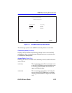
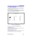
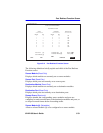
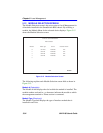
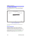
5.11 PORT REDIRECT FUNCTION SCREEN
The Port Redirect Function screen, Figure 5-14, allows the user to set
each one of the modules in the chassis (1 through 5), and the ports of the
corresponding module installed, as a source or destination port. A port
can be set to have one or more destination ports and chassis module slot
numbers. For example, port 1 in module (slot) 1 can be set as a source
port with three destinations, ports 2, 3, and 4 in module (slot) 3. Traffic
from port 1 in module 1 is then automatically redirected to ports 2, 3, and
4 in module 3. Port 1 in module 1 can also serve as a destination port for
other ports and modules. The port redirect function is extremely useful for
troubleshooting purposes, as it allows traffic to be sent to a particular
port(s) where, with the use of an analyzer or RMON probe, all current
traffic from the source port(s) can be examined.
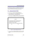
Access the Port Redirect Function screen from the Chassis Menu screen
by using the arrow keys to highlight the PORT REDIRECT
FUNCTION menu item and pressing ENTER. The Port Redirect
Function screen, Figure 5-14, displays.
NOTE
The Port Redirect Function screen may not be available
depending on the operational mode that has been set for the
chassis. Refer to your Release Notes to see what operational
modes support the Port Redirect Function. Refer to
Section 5.7.7, Setting the Operational Mode, for instructions
on configuring the operational mode of all the modules installed
in the chassis.
NOTES
The module number corresponds to the slot number in which
the module resides in the 6C105 chassis (1 through 5).
Although traffic from the source port (including, if desired,
errored frames) is sent to the destination port, normal switching
is still performed for all frames on the source port.