


Problem Solving 5-5
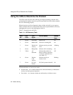
Using the LEDs to Determine the Problem
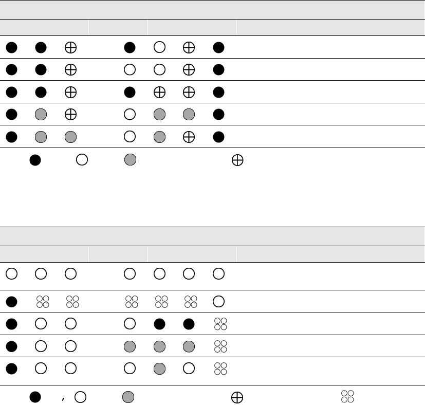
Table 5-3, Table 5-4, and Table 5-5 list common conditions and the corresponding
states of the LED indicators.
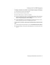
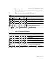
Table 5-3: Normal Operating Mode LED Patterns
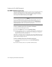
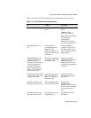
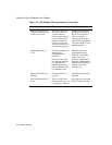
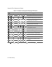
Table 5-4: Diagnostics LED Patterns
LEDs
1
1. =on, =off, =steady blinking, =random blinking
1 2 3 4 5 6 7 Meaning of LED Pattern
Normal operating mode.
AP is okay but waiting for Spanning Tree.
AP is okay but occasionally saturated.
PC Card is defective.
Ethernet problem after power-up.
LEDs
1
1. =on =off, =steady blinking, =random blinking, =any state
1 2 3 4 5 6 7 Meaning of LED Pattern
No power. (No power at the outlet or a failed
power supply.)
PC Card not inserted properly.
Diagnostics are running.
Ethernet connection broken.
Failure while initializing/testing the
memory.