


SmartCell 6A000 User Guide 2-7
Switch Installation and Setup Confi
g
urin
g
the Switch
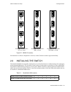
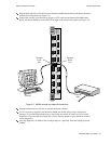
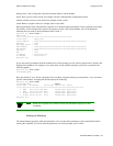
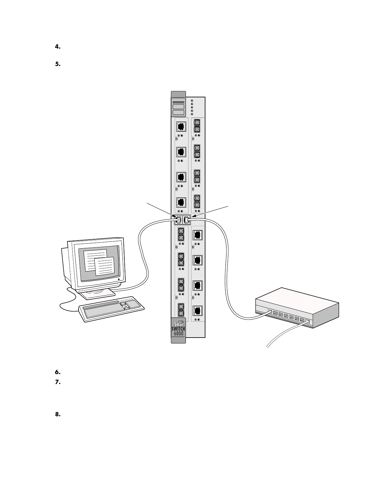
Plug the other end of the UTP cable into the SmartCell 6A000 female RJ-45 jack labeled Terminal,
located on the front panel (see Figure 2-5).
Connect the switch to your network by plugging a UTP cable into the SmartCell 6A000 female
RJ-45 jack labeled Ethernet, located at the lower right of the switch's front panel (see Figure 2-5).
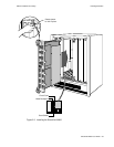
Fi
g
ure 2-5 6A000 console and network connections
Start the dumb terminal or PC and its terminal emulation software.
As soon as power is applied to the SmartCell 6A000, the module emits a series of diagnostic
messages. If you inserted the module into a chassis that was turned off, turn it on now to see the
diagnostics. If you inserted the module into a chassis that was turned on, press the Reset switch to
see the diagnostics.
After the diagnostics are finished, the switch prompts for a password. Enter the default password,
"admin."
Terminal
Ethernet
Hub
Terminal
RJ-45
Port
Ethernet
RJ-45
Port
NO SYNC
DATA
NO SYNC
DATA
1 2 3
4
1234
6A-IOM-21-4
6A-IOM-22-4
NO SYNC
DATA
NO SYNC
DATA
1 2 3
4
1234
6A-IOM-21-4
6A-IOM-22-4
ATM
FAIL
STATUS
POWER
RX ENET
TX ENET
S
Y
S
T
E
M