


SmartCell 6A000 User Guide 4-7
Switch Administration Settin
g
Up Routes
For example, create a default IISP route from port B1.
SmartCell ZX# add iisproute
AtmAddress() :
< no netprefix specified
PortNumber(A1) : b1
Metric(1) :
SmartCell ZX#
To see the route in the SmartCell 6A000 routing table, enter the following:
Top # show iisp
EntryNum PortNum Metric Length ATM Address
============================================================================
0 B1 1 0 default route
SmartCell ZX#
Default IISP routes are used primarily as gateway connections to other LAN segments or to a WAN connection. For
instance, a SmartCell 6A000 contains four standard IISP routes and one default IISP route. If a connection is being
established whose address does not correspond to one of the four standard IISP routes, the connection is automatically
forwarded to the default IISP route.
Because of the default IISP route's lack of a definite ATM address, be careful when using these routes. Observe the
following rules when using default IISP routes:
• Never add more than one default IISP route on any SmartCell 6A000.
• Do not use default IISP routes as an "easy" way to create a route between two devices.
• Do not over use default IISP routes. Doing so can create overly complicated network topologies.
• When using IISP routes, be careful not to create ambiguous routes or routing loops.
• Restrict the use of default IISP routes to gateway connections out of the local LAN segment.
IISP Routes and Network Topolo
gy
IISP is implemented on the SmartCell 6A000 switch so that a route's destination address is some sequential portion
(always starting with the first byte) of a 20-byte ATM address. Usually, the default netprefix is used (first thirteen
bytes). However, routes can be defined using more or fewer bytes than the thirteen netprefix bytes.
This ability to define destination addresses by masking off portions of an ATM address allows multiple SmartCell
6A000 switches to be connected in flexible configurations. Furthermore, you can change the netprefix of a switch (or
a port on a switch) to any value by using the
set netprefix command. Combining these two capabilities, you can
define routes with simple addressing schemes and create hierarchical network topologies.
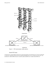
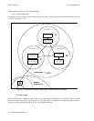
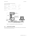
For example, Figure 4-2 shows three groups of switches: A, B and C. Use the
set netprefix. command to change
the first two bytes of the netprefix for switches within A, B, and C to 11:22.
Add a third byte to the netprefix of each group (a group identifier), such that
• Group A = 11:22:33
• Group B = 11:22:44
• Group C = 11:22:55
Within each group, add one more byte to each switch address (a switch identifier). Each switch (route destination) can
now be specified by
11:22: + group identifier byte + switch identifier byte
For example, switches in group A are 11:22:33:00 and 11:22:33:01