


SmartCell 6A000 User Guide Appendix A-1
APPENDIX A FEATURES AND
SPECIFICATIONS
This appendix describes SmartCell 6A000 switch hardware information, product features, technical specifications, and
adapter pin-out descriptions.
A.1 HARDWARE COMPONENTS
This section describes the hardware components of the SmartCell 6A000 ATM switch.
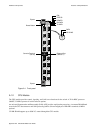
A.1.1 Front Panel
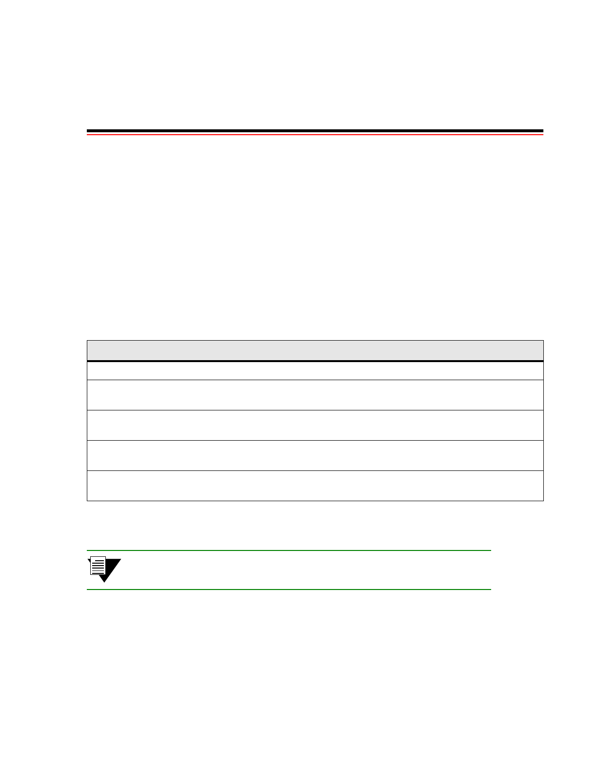
Table A-1 tells how to read the LEDs on the front panel.
Note The ‘MON' and ‘DIAG' functions are not used in this release.
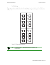
Figure A-1 illustrates the front panel of the SmartCell 6A000 switch.
Table A-1 Front panel LEDs
LED Function
FAIL (red) Normally OFF; ON indicates CPU failed.
STATUS
(amber)
Normally OFF; ON indicates an error condition that prevents alarm information from being
displayed to the console.
POWER
(green)
Normally ON; OFF indicates the CPU is receiving power from the power supply.
RX DATA
(green)
Normally FLASHING intermittently if there is receive activity on the port; indicates the Ethernet
port is up and receiving Ethernet frames.
TX DATA
(green)
Normally FLASHING intermittently if there is transmit activity on the port; indicates the Ethernet
port is up and transmitting Ethernet frames.