


3-4 SmartCell 6A000 User Guide
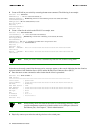
2. Create an ELAN on your switch by executing the add elan command. The following is an example:
SmartCell ZX # add elan
ELANNumber(0) : 1
use 1 instead of the default, (0)
ELANName(ELAN000) : Marketing
ELAN is named Marketing instead of the default, (ELAN000)
ConnectMethod(SVC):
ELANType(802.3)
< The default (Ethernet) is used
Multipoint(YES) :
MTU(1516) :
Distribute(PROXY) :
SmartCell ZX #
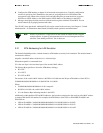
3. Create a client for the switch on the ELAN. For example, enter
SmartCell ZX # add laneclient
ClientNumber(0) : 1
< one is used instead of the default, (0)
LanName(ELAN001) : Marketing
< ELAN name is Marketing, not the default, (ELAN001)
ServerType(LECS) :
ServerAddress() :
IPAddress() : 90.1.1.1
< IP address and subnet mask is assigned to the client
NetMask(255.0.0.0): 255.255.255.0
MTU(1516) :
SmartCell ZX #
NOTICE - 'ZLESSRV' LES Join 39:00:00:00:00:00:00:00:00:00:14:41:80:00:20:D4:
14:41:82:00
NOTICE - 'ZLESSRV' BUS Connect 39:00:00:00:00:00:00:00:00:00:14:41:80:00:20:D4:
14:41:82:00
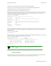
Note When you create a client, it automatically finds the LECS address using ILMI.
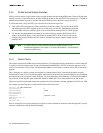
Notice that as the newly created client becomes active, messages appear on the console indicating that the client has
registered with the LAN Emulation Server (LES) and the Broadcast and Unknown Sever (BUS).
4. Enter the show client command to make certain that the client is operational.
SmartCell ZX # show client 1
LANE Client 1
============================================================================
Client State : Operational
Client Address : 39:00:00:00:00:00:00:00:00:00:14:41:80:00:20:D4:14:41:81:00
LAN Name : Marketing
LECS Addr Source : ILMI
LECS Address : 39:00:00:00:00:00:00:00:00:00:14:41:80:00:20:D4:14:41:80:01
LES Address : 39:00:00:00:00:00:00:00:00:00:14:41:80:00:20:D4:14:41:82:02
LAN Type : 802.3
MTU : 1516
IP Address : 90.1.1.1
IP NetMask : 255.255.255.0
SmartCell ZX #
Note While creating an ELAN client for the switch is not absolutely necessary, it does
provide management connectivity with the switch over its ATM ports (instead of
the Ethernet port). See Chapter 4, "Switch Administration."
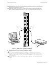
5. Physically connect your end nodes and edge devices to the switch ports.