


4-14 SmartCell 6A000 User Guide
Settin
g
Up PVC Connections Switch Administration
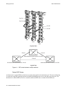
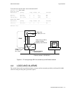
4.5.1 Point-to-Point PVCs
The procedure for setting up a PVC between two end nodes through the SmartCell 6A000 consists of specifying the
ports and the virtual path and virtual channel identifiers (VPI and VCI).
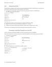
1. Use add pvc to create the PVC; specify the ports through which the connection is established and
the VPI/VCI pair to use with each port.
SmartCell ZX # add pvc
ConnType(PTP) :
LowPort(A1) : c1
<specify port C1
LowVPI(0) :
<accept the default VPI, 0
LowVCI(33) : 100
<use 100 for VCI
HighPort(A1) : b2
<specify port B2
HighVPI(0) :
HighVCI(34) : 100
FwdTrafficDescriptorIndex(1) :
BkwTrafficDescriptorIndex(1) :
SmartCell ZX #
The example above creates a PVC between ports C1 and B2 with VPI/VCI = 0/100.
2. Plug the end nodes into the specified SmartCell 6A000 ports (C1 and B2).
3. Configure each end node with the proper IP address, subnet mask, and VPI/VCI pair = 0/100.
The end nodes can communicate with each other through the point-to-point PVC connection.
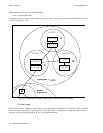
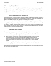
Connectin
g
to Local Client Throu
g
h Point-to-Point PVC
All PVC connections to SmartCell 6A000 local clients use B4 (the CPU port) as the HighPort.
Follow these instructions to connect an end node to a SmartCell 6A000 local client through a point-to-point PVC.
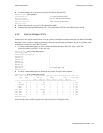
1. Use add pvc to create the PVC.
SmartCell ZX # add pvc
ConnType(PTP) :
<use a point-to-point PVC
LowPort(A1) :
<use port A1 in this example
LowVPI(0) :
LowVCI(33) : 100
HighPort(A1) : b4
<HighPort must be B4
HighVPI(0) :
HighVCI(34) : 100
FwdTrafficDescriptorIndex(1) :
BkwTrafficDescriptorIndex(1) :
SmartCell ZX #
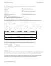
2. Use add ipatmclient to create the IP over ATM local client.
SmartCell ZX # add ipatmclient
ClientNumber(0) : 2
<use client # 2 in this example
ServerType(NONE) :
<accept default
ServerAddress() :
IPAddress() : 10.1.1.0
NetMask(255.0.0.0) :
MTU(9180) :
SmartCell ZX #