


3-2 SmartCell 6A000 User Guide
Note End nodes do not need to be physically attached to the switch that contains the
ARP server. For example, an end station is connected to a SmartCell 6A000
switch that is connected through an IISP route to the switch containing the ARP
server. No special configuration is needed for this end station to participate in the
VLAN because the end station automatically finds its path across the IISP route
to communicate with the ARP server and the other VLAN members.
5. Configure the ATM interface or adapter for end nodes and edge devices. Typically, configuration
consists of designating IP over ATM as the protocol, assigning the device an IP address, and
specifying the 20-byte ATM address of the ARP server (the switch's client address).
6. As your end devices are configured and started, they register with the ARP server. You can test
whether your IP over ATM VLAN is functional by pinging from one end device to another.
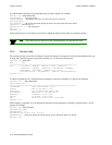
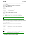
7. To make certain that all end devices are registered with the ARP server, you can inspect the switch's
ARP table using the
show ipatmarp command. For example, if three end devices with IP addresses
90.1.1.2, 90.1.1.3, and 90.1.1.4 are added to the VLAN, the following ARP table entries should
exist:
SmartCell ZX # show ipatmarp
ClientNumber(ALL) :
IP/ATM Server 1 ARP Table
IP Address ATM Address
============================================================================
90.1.1.2 39:00:00:00:00:00:00:00:00:00:14:41:80:00:00:5A:01:01:02:00
IP/ATM Server 3 ARP Table
IP Address ATM Address
============================================================================
90.1.1.3 39:00:00:00:00:00:00:00:00:00:14:41:80:00:00:5A:01:01:03:00
IP/ATM Server 5 ARP Table
IP Address ATM Address
============================================================================
90.1.1.4 39:00:00:00:00:00:00:00:00:00:14:41:80:00:00:5A:01:01:04:00
SmartCell ZX #
3.1.1 ATM Addressin
g
for IP over ATM
The SmartCell 6A000 uses a default form for ATM addresses in IP over ATM. The default format is constructed as
follows:
netprefix + two zero bytes + IP address of the device (in hex) + a trailing zero byte
Where the netprefix is constructed from
39 + nine zero bytes + the last three bytes of the device's MAC address
For instance, if the switch MAC address is 00:20:D4:14:41:80 and its client IP address is the one used in the example
in step 2, then the 20-byte ATM address of the ARP server is
39:00:00:00:00:00:00:00:00:00:14:41:80:00:00:5A:01:01:01:00
Where
• 39:00:00:00:00:00:00:00:00:00:14:41:80 = netprefix
• 00:00 = two trailing zeros