


SmartCell 6A000 User Guide Appendix A-3
Features and Specifications Hardware Components
The flash RAM provides persistent storage of bootup addresses and operations, configuration data, and system
software. Four megabytes of flash RAM is standard; 8 MB is optional.
Field-upgradeable DRAM and flash memory, mounted in standard sockets, enable future software enhancements.
An Ethernet port provides connection to the switch for LAN-based switch management functions. An RS-232 console
port provides connection for local configuration and maintenance functions.
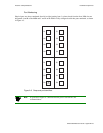
A.1.3 Switch Modules (MSM and ESM)
The Main Switch Module (MSM) contains the primary cell-switching fabric. The MSM provides switching for four
4-port I/O modules; however, only two I/O modules (8 ports) are physically connected to the MSM. In addition, one
of these 8 ports (B4) is reserved for CPU functions, yielding an effective total of 7 user ports (port numbers A1-A4
and B1-B3). For configurations requiring more than 7 user ports, an additional Expansion Switch Module (ESM) must
be added, for a total of 15 user ports. Using a shared memory architecture, the MSM utilizes fast SRAM buffering
onboard. The MSM has 32K cells.
The ESM is a switch-expansion module that provides switch fabric for an additional 8 ports, expanding the switch from
7 to 15 ports. It provides connections for up to two I/O modules.
Caution If an ESM is not installed, sheet metal blanks must cover the front slot opening,
maintaining EMI integrity and proper airflow.
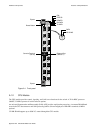
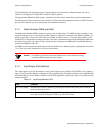
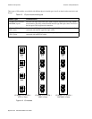
A.1.4 Input/Output (Port) Modules
The switch supports up to four I/O modules, each of which supports four 155 Mbps STS-3c/STM-1 ports, yielding a
total of 15 user ports (the 16th port is dedicated to CPU communication). The physical interfaces are compatible with
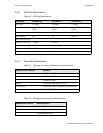
ATM Forum Physical Layer, BellCore SONET, and ITU SDH applicable specifications. Table A-2 describes the I/O
module port LEDs.
Table A-2 Input/Output Module LEDs
LED Function
NO SYNC (amber) Normally OFF; when lit, indicates a physical layer Out Of Frame (OOF) error condition is
present on the port (receive).
DATA (green) Normally FLASHING if there is receive activity on the port; indicates the port is up and
receiving cell traffic. Solid green if link is up, off if link is down.