


Tag Switching 9-19
Configuration Example
Configuration Example
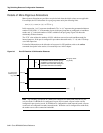
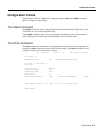
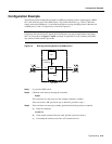
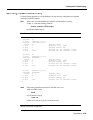
The following initial configuration example for a BPX tag switching router is with respect to a BXM
OC3 card located in slot 4 of the BPX switch, a Tag Switch Controller (e.g., 7500 or 7200 series
router) connected to BXM port 4.1, and with connections to two tag switching routers in the network
at BXM ports 4.2 and 4.3, respectively, as shown in Figure 9-9.
Note Whether a BXM card operates in trunk or port mode is determined by how the first port is
brought up. Once the first port is upped, the following ports can only be upped in the same mode,
that is by using either the upport or uptrk command, as applicable. For tag switching, the BXM
may operate in either trunk or port mode.
Figure 9-9 BPX Tag Switching Router with BXM in Slot 4
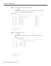
Step 1 Log in to the BPX switch.
Step 2 Check the card status by entering the command:
dspcds
The card status, for card in slot 4 in this example, should be “standby”.
If the card status is OK, proceed to step 4, otherwise, proceed to step 3.
Step 3 If the card does not come up in standby, perform the following actions as required:
(a) Enter the command
resetcd 4 h
(b) If the resetcd command does not work, pull the card and re-insert it.
(c) If reseating the card does not work, call Customer Service.
TSC
BXM
4.1
4.2
4.3
TVCs
TVCs
S6873
BPX
Master/slave
control link
BPX TSRBPX TSR
BPX TSR