


Operation
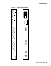
AT3-6ME Interface Adapter D-7
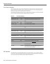
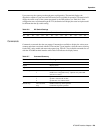
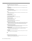
Table D-4 DIP Switch SW-2 Selection Guide
BPX, IGX, or IPX Port Configuration
The trunk on the BPX, IGX, or IPX node must be reconfigured from Cisco StrataView Plus or a local
control terminal.
Step 1 Telnet to the first node equipped with an AT3-6ME.
Step 2 Use the Configure Trunk (cnftrk) command to select T2 for the Tx Trunk Rate.
Step 3 Set the RCV Trunk Rate to 28980 cps.
Step 4 Repeat steps 1 through 3 for all other nodes using the AT3-6ME.
Operation
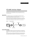
The following paragraphs describe the various operating modes for the AT3-6ME. The unit is
basically designed for unattended operation. Any failures in the unit or any line alarms or errors will
be propagated.
Power-Up Sequence
During the system power-up, the unit goes through a self test procedure. The Power LED turns green.
The Active/ Fail LED stays off until the self test sequence is completed. At the end of the self test
the loop LED comes on for about 5 seconds.
Switches Position Function
1
2
Up
Up
Internal synchronization source for the T2 transmitter
1
2
Up
Down
Slave T2 transmitter to T3 line
1
2
Down
Down
Slave T2 transmitter to T2 receiver
3
4
Up
Up
Long length T3 cable
3
4
Up
Down
Medium length T3 cable
3
4
Down
Down
Short length T3 cable; system is co located to IPX/IGX/BPX
1
(default)
1. T2 and T3 cable length should be set to “short” upon power-up for self-test.
Upon LOS, defaults to “internal synchronization.”
5, 6 don’t care Unused
7UpATM converter mode
7DownTest Mode
8 Up Enable BPV relay from T2 to T3
8 Down Disable PV relay from T2 to T3
9 Up Long length T2 cable
9 Down Short length T2 cable (default)
1
10, 11, 12 Don’t care Unused