


1-24 Cisco BPX 8600 Series Reference
Switch Availability
Switch Availability
Hardware and software components are designed to provide a switch availability in excess of
99.99%. Network availability will be impacted by link failure, which has a higher probability of
occurrence, than equipment failure.
Because of this, Cisco WAN network switches are designed so that connections are automatically
rerouted around network trunk failures often before users detect a problem. System faults are
detected and corrective action taken often before they become service affecting. The following
paragraphs describe some of the features that contribute to network availability.
Node Redundancy
System availability is a primary requirement with the BPX switch. The designed availability factor
of a BPX switch is (99.99%) based on a node equipped with optional redundancy and a network
designed with alternate routing available. The system software, as well as firmware for each
individual system module, incorporates various diagnostic and self-test routines to monitor the node
for proper operation and availability of backup hardware.
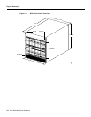
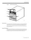
For protection against hardware failure, a BPX switch shelf can be equipped with the following
redundancy options:
• Redundant common control modules
• Redundant crosspoint switch matrixes
• Redundant high-speed data and control lines
• Redundant power supplies
• Redundant high-speed network interface cards
• Redundant service interface cards
If redundancy is provided for a BPX switch, when a hardware failure occurs, a hot-standby module
is automatically switched into service, replacing the failed module. All cards are hot-pluggable, so
replacing a failed card in a redundant system can be performed without disrupting service.
Since the power supplies share the power load, redundant supplies are not idle. All power supplies
are active; if one fails, then the others pick up its load. The power supply subsystem is sized so that
if any one supply fails, the node will continue to be supplied with adequate power to maintain normal
operation of the node. The node monitors each power supply voltage output and measures cabinet
temperature to be displayed on the NMS terminal or other system terminal.
Node Alarms
Each BPX switch shelf within the network runs continuous background diagnostics to verify the
proper operation of all active and standby cards, backplane control, data, and clock lines, cabinet
temperature, and power supplies. These background tests are transparent to normal network
operation.
Each card in the node has front-panel LEDs to indicate active, failed, or standby status. Each power
supply has green LEDs to indicate proper voltage input and output. An Alarm, Status, and Monitor
card collects all the node hardware status conditions and reports it using front panel LED indicators
and alarm closures. Indicators are provided for major alarm, minor alarm, ACO, power supply status,
and alarm history. Alarm relay contact closures for major and minor alarms are available from each
node through a 15-pin D-type connector for forwarding to a site alarm system.