


9-22 Cisco BPX 8600 Series Reference
Configuration Example
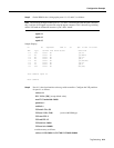
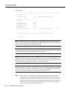
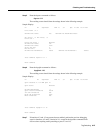
Sample Display:
n4 TN SuperUser BPX 15 9.1 Apr. 4 1998 16:40 PST
Port/Trunk : 4.1
Maximum PVC LCNS: 256 Maximum PVC Bandwidth:26000
Min Lcn(1) : 0 Min Lcn(2) : 0
Partition 1
Partition State : Enabled
Minimum VSI LCNS: 512
Maximum VSI LCNS: 7048
Start VSI VPI: 2
End VSI VPI : 15
Minimum VSI Bandwidth : 26000 Maximum VSI Bandwidth : 100000
Last Command: cnfrsrc 4.1 256 26000 1 e 512 7048 2 15 26000 100000
Next Command:
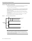
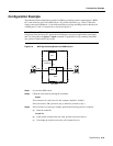
Note It is possible to have PVCs terminating on the Tag Switch Controller itself, as shown in
Figure 9-4. This example reserves approximately 10 Mbps (26000 cells/sec) for PVCs, and allows
up to 256 PVCs on the switch port connected to the TSC.
Note The VSI max and min logical connections (LCNs) will determine the maximum number of
tag virtual connections (TVCs) that can be supported on the interface. The number of TVCs required
on the interface depends on the routing topology of the tag switch.
Note By default the TSC will use either a starting VSI VPI of 1 or 2 for tag switching, whichever
is available. If both are available, a starting VSI VPI of 1 is used. The VPI range should be 2-3 on a
BPX VSI connected to a 7200 or 7500 AIP. If VPI 2 is not to be used, the tag switching VPI interface
configuration command can be used on the TSC to override the defaults
Note The VSI range for tag switching on the BPX switch is configured as a VSI partition, usually
VSI partition number 1. VSI VPI 1 is reserved for autoroute, so the VSI partition for tag switching
should start at VPI 2. Two VPIs are sufficient for the current release, although it may be advisable
to reserve a larger range of VPIs for later expansion, for example, VPIs 2-15.
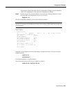
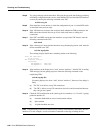
Step 7 Ports 4.2 and 4.3 are connected to other tag switch router ports in this example and
support TVCs across the network. Configure the VSI partitions for ports 4.2 and 4.3 by
repeating the procedures in the previous step, but entering 4.2 and 4.3, where applicable.
Maximum VSI LCNs (logical connection numbers) determine the number of connections
that can be made to each port. For a description of how the LCNs may be assigned to a
port, refer to Configuring VSI LCNS on page 12.