


BME Multicasting 10-5
BME Operation
Cell Replication Stats
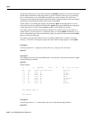
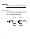
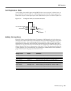
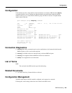
As an example of how traffic appears on the BME, if there is one root at port 1 with two leaves at
port 2, and traffic is passed on the root at 500 cells/sec, then one should see an egress port stat of
1000 cell/sec on port 1 and an ingress port stat of 1000 cells/sec on port 2, as shown in Figure 10-2.
Figure 10-2 Example of Traffic, one root and two leaves
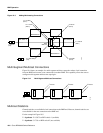
Adding Connections
Figure 10-3 shows two multicasting groups. For purposes of the illustration only a few leaves are
shown for each connection. However, as described previously, each multicasting group could contain
up to 8064 connections. Also, in this example, the two connections with a VCI of 0 each define a
multicasting root connection. Their VPI defines a broadcasting group. For example, one group is
defined by 2.1.70.0, where the VCI of zero defines the root connection to a BME, and the VPI of 70
defines a group. All the leaves in that group are of the form 2.2.70.x. The other group is defined by
2.2.80.0, where the VCI of zero defines the root connection to a BME, and the VPI of 80 defines a
group. All the leaves in that group are of the form 2.1.80.x.
Group 2.1.70.x Action Command
at bpx switch_F, add input to root addcon 2.1.70.0 bpx switch_A 1.1.80.100 c 500 * * *
at bpx switch_F, add leaf 1 addcon 2.2.70.101 bpx switch_D 6.1.100.50 c 500 * * *
at bpx switch_F, add leaf 2 addcon 2.2.70.100 bpx switch_C 4.3.50.60 c 500 * * *
at bpx switch_F, add leaf 3 addcon 2.2.70.102 bpx switch_G 3.4.55.75 c 500 * * *
Group 2.2.80.x
at bpx switch_F, add input to root addcon 2.2.80.0 bpx switch_B 10.1.233.400 v 4000 * * *
at bpx switch_F, add leaf 1 addcon 2.1.80.201 bpx switch_E 13.1.78.900 v 4000 * * *
at bpx switch_F, add leaf 2 addcon 2.1.80.100 bpx switch_E 14.1.100.40 v 4000 * * *
BME
root 500 cells/sec
1000 cells/sec
Port 1
Port 2
leaf 1
500 cells/sec
leaf 2
500 cells/sec
11734