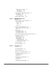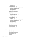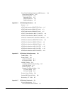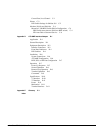
Table of Contents vii
Front Panel Description 3-12
Line Module for the Alarm/Status Monitor Card 3-15
BPX Switch StrataBus 9.6 and 19.2 Gbps Backplanes 3-17
Chapter 4 Network Interface (Trunk) Cards 4-1
BPX Switch Network Interface Group 4-1
BXM Cards, Trunk Mode Summary 4-1
Broadband Network Interface Cards (BNI-T3 and BNI-E3) 4-2
Features 4-3
Functional Description 4-3
Egress 4-3
Ingress 4-4
Bandwidth Control 4-5
Loopbacks and Diagnostics 4-6
Front Panel Indicators 4-6
T3 and E3 Line Modules (LM-3T3 and LM-3E3) 4-8
Broadband Network Interface Cards, BNI-155 4-11
Features 4-11
Overview 4-11
Functional Description 4-12
Front Panel Indicators 4-13
OC3, Line Modules (SMF, SMFLR, & MMF) 4-16
Y-Cabling of BNI Backcard, SMF-2-BC 4-19
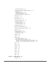
Chapter 5 Service Interface (Line) Cards 5-1
BPX Switch Service Interface Group Summary 5-1
BXM Cards, Port (UNI) Mode Summary 5-1
ASI-1, ATM Service Interface Card 5-2
Features 5-3
Functional Description 5-3
Configuring Connections (ATM over ASI Example) 5-4
Monitoring Statistics 5-5
Front Panel Description 5-5
LM-2T3 Module 5-8
LM-2E3 Module 5-10
ASI-155, ATM Service Interface Card 5-12
Features 5-12
Overview 5-12
Configuring Connections 5-13
Functional Description 5-13
Monitoring Statistics 5-14
Front Panel Indicators 5-14
ASI-155 Line Module, LM-2OC3-SMF 5-17


