


D-2 Cisco BPX 8600 Series Reference
Equipment Description
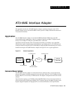
ATM cells from one interface are mapped to the other interface enabling users with ATM node
equipment with North American T3 ATM ports to operate in a T2 network. The ATM cell throughput
on a T2 digital trunk using this adapter is limited to 14,490 cells per second.
The cell transfer rate for T2 is greatly reduced from the T3 cell rate out of a T3 port on an IPX using
the ATMT card or from a BPX port. It is very important to restrict the cell rate from the node when
using a T2 trunk. Cell rate adaptation is done via software trunk configuration at the T3 ATM
interface, where the non null cell throughput is limited to the T2 capacity. In the T2 to the T3
direction, the T3 ATM interface has more than enough capacity to accommodate the T2 cell rate.
The Interface Adapter can buffer a 70-cell burst at the T3 rate before the T2 interface will begin to
drop cells. Cells will continue to be dropped until the T3 interface returns to a rate that complies with
the bandwidth of the T2 interface.
All alarms and line errors are passed through the Interface Adapter unchanged. Any existing network
management system has an instant view of the actual network transmission system. Errors at the
ATM layer propagate through from one interface to the other, thus the end user has the complete
knowledge and statistical information regarding the network status at all times. Therefore a special
network management interface is not required.
Since the T3 interface is asynchronous and the T2 is synchronous, the AT3-6ME can be configured
to carry the synchronization information through from one interface to the other. The
synchronization is carried through the T3 interface using the PLCP-embedded 8 KHz. The T2
interface clock may be generated locally or it may be slaved to the public network.
Equipment Description
The AT3-6ME is fully contained in a metallic housing designed to be mounted in a 19" equipment
rack. It occupies only one rack mounting space and is powered from normal AC line powering. The
power supply accommodates an input voltage over the range 90 to 240 VAC, 50 or 60 Hz.
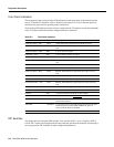
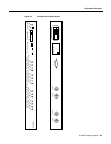
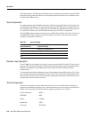
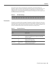
Interface Connectors
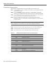
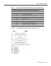
The interface connectors are located on the rear panel (see Table D-1 and Figure D-2). These
connectors include:
• Two T3 BNC connectors, XMT and RCV.
• Two 6M BNC connectors, XMT and RCV.
• A single RS-232 male, subminiature 9-pin control terminal interface.
• AC input connector with integral fuse.
The control terminal is a standard RS-232 interface DTE interface. No hardware handshake is
required for the interface. The diagnostic display comes up immediately. It operates at 9.6 Kbps with
any ASCII terminal.