


Modems, Dial-In and Dial-Out
BPX Switch Peripherals C-5
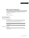
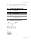
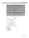
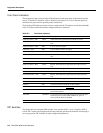
Step 6 Connect the modem to the BPX CONTROL port using a null-modem cables Figure C-1.
A null modem cable is used, as the connection is essentially a DCE to DCE rather than a
DTE to DCE connection.
Step 7 Ask customer service to assist in testing the operation of the modem setup.
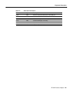
Table C-7 V.34R Modem Configuration for Auto-Answer (Dial-in to BPX)
Figure C-1 Dial-Modem Cabling for Auto Answer (Dial-In to BPX)
Step Command Function
1. AT & F Reset to factory default.
2 ATL1 Set modem loudness, modem speaker at low volume.
3. ATSØ=1 Enables Auto-Answer Mode on modem (answer on first ring).
4 AT\N3 Enables automatic MNP error correction.
5 AT%C Disables data compression.
6. AT\QØ Disables XON/XOFF flow control.
7. AT&S1 Sets DSR to "normal".
8. ATEØ Disables local character echo. Modem will not echo what you type.
9. ATQ1 Disables result codes. (Modem will appear “dead”, will stop
responding “OK” to commands.)
10. AT&W Saves current configuration settings in non-volatile memory. (Writes
and stores to configuration location 1.)
Control
port
Modem
connector
1
2
3
4
5
6
20
7
1
2
3
4
5
6
20
7
FG
TXD
RXD
RTS
CTS
DSR
DTR
SG
Legend
FG - Frame Ground
TXD - Transmit Data
RXD - Receive Data
RTS - Request To Send
CTS - Clear To Send
DSR - Data Set Ready
DTR - Data Terminal Ready
CD - Carrier Detect
SG - Signal Ground
12138