


Repair and Replacement 11-13
Replacing Parts
Step 5 Screw in the thumb-screw on the right side of the power supply assembly until it is finger
tight.
Step 6 Flip the retaining bracket up and tighten its thumbscrew.
Step 7 Reinstall the Air Intake Grille and press firmly on the top, center of the Air Intake Grille
until the latch snaps into place.
Step 8 Check the status and output voltage of the replacement power supply using the dspasm
command. Make sure the status is OK and the output voltage is 48V.
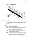
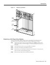
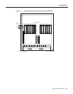
Replacing the Fan Assembly
The Fan Assembly provides the primary cooling for the BPX switch and is located at the top, rear of
the BPX switch cabinet. There are three fans in the Fan Assembly. The fan on the right (number 1)
and the one on the left (number 3) can be changed out individually with very little effort or
interruption in the operation of the node. The fan in the middle (number 2) requires powering down
the node and removing the Fan Assembly to replace.
Caution You must work quickly but carefully to prevent heat buildup in the node which could damage the
cards.
To replace fan number 1 or number 3 in the Fan Assembly, perform the following steps:
Step 1 Use the dspasm command to check the status of the three fans.
Step 2 From the rear of the BPX switch, visually check that the fan(s) is indeed not turning or
turning slowly.
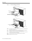
Step 3 From the back of the cabinet, unplug the small fan power cord from its appropriate
receptacle on the Fan Assembly.
Step 4 Remove the two screws holding the fan and the fan shield to the-fan housing. Be careful
not to drop the hardware into the rear of the cabinet.
Step 5 Remove the fan. Replace the fan in reverse order. Use the existing fan grille.
To replace fan number 2 requires powering down the node and replacing the whole Fan Assembly.
Under normal ambient room temperatures, this can be scheduled for the next available quiet time.
Perform the following steps:
Step 1 Use the dspasm command to check the status of the three fans.
Step 2 From the rear of the BPX switch, visually check that fan number 2 is not turning or
turning slowly.
Step 3 At the rear of the BPX switch, turn the circuit breaker(s) OFF to power down the node.
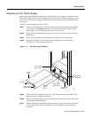
Step 4 Loosen the eight captive screws holding the Fan Assembly in place.
Step 5 With one hand, pull the Fan Assembly back just far enough to gain access to the Fan
Assembly power cord. This cord connects to the Fan Assembly to the backplane.
Step 6 Unplug the power cord and remove the Fan Assembly.
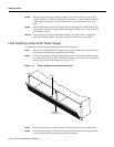
Step 7 Plug the power cord in the replacement Fan Assembly into the backplane connector.
Step 8 Install the replacement Fan Assembly.
Step 9 Tighten the eight screws holding the Fan Assembly in place.