


14-2 Cisco BPX 8600 Series Reference
SNMP Overview
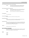
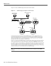
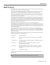
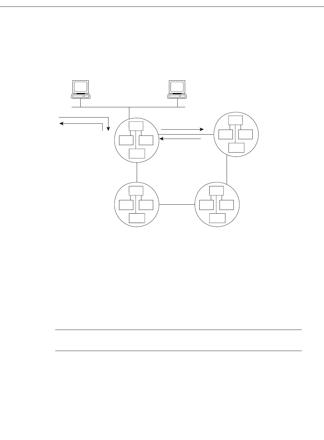
Figure 14-1 shows an SNMP manager and the nodes within a domain.
Figure 14-1 SNMP Manager and Agents in a BPX Domain
Communication between the agents and the SNMP manager uses the standard UDP protocol
encapsulated within IP protocol. The communication link between the SNMP manager and the
directly attached BPX node uses the Ethernet interface of an BCC processor card. The SNMP
manager can be either local or remote to the BPX node.
Figure 14-1 illustrates the SNMP manager’s communication with the agents in the network. Each
node in the domain must have a network IP address assigned by the cnfnwip command (see the
Cisco WAN Switching Command Reference publication for details). The manager uses the network
IP address to address an agent in the domain. The directly attached node (Node 4 in Figure 14-1)
directs the SNMP message to the addressed BPX node. Responses from the agent go to the directly
attached node then pass over the Ethernet link to the SNMP manager.
Note The LAN IP address of the directly attached node must be configured with the cnflan
command.
SV
+
workstation
(SNMP manager)
BPX node 4
BPX node 1
BPX node 3
BPX node 2
H8183
SNMP requests
SNMP responses
SNMP requests
SNMP responses
SNMP
agent
STD
MIB II
Prop.
MIB
ATM UNI
3.1 MIB
SNMP
agent
STD
MIB II
Prop.
MIB
ATM UNI
3.1 MIB
SNMP
agent
STD
MIB II
Prop.
MIB
ATM UNI
3.1 MIB
SNMP
agent
STD
MIB II
Prop.
MIB
ATM UNI
3.1 MIB
SNMP management
platform