


11-12 Cisco BPX 8600 Series Reference
Replacing Parts
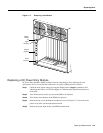
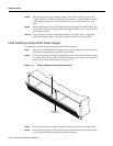
Step 8 There are two power supply securing fasteners, one on each side of the power supply
assembly (Figure 11-4). The one on the left of each supply is a spring-loaded pin, the one
on the right of each supply is a normal thumb-screw. Loosen the thumb-screw on the
right.
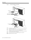
Step 9 With the right hand, grip the power supply under the front panel. With the left hand, pull
out the spring-loaded pin on the left side of the supply and hold it out as you pull out the
power supply assembly.
Step 10 The power supply assembly weighs approximately 15 pounds (33 Kgs.). Support the
bottom of the power supply as you pull it straight out, until it is free of the shelf.
Field-Installing a Second AC Power Supply
To field-install a redundant power supply, perform the following steps:
Step 1 If the front Air Intake Grille has already been removed, go to the next step. If not, remove
it using Step 2 through Step 6 of the previous procedure.
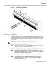
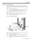
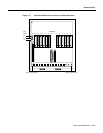
Step 2 If converting a node from single to redundant powering, first remove the blank filler panel
over position B (right side). With Air Intake Grille open, remove three screws attaching
the filler panel to the retainer bracket (see Figure 11-5).
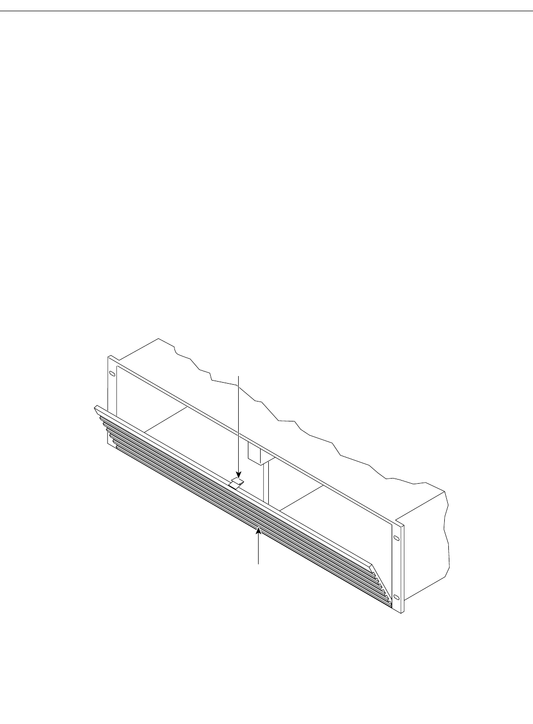
Figure 11-5 Removing Blank Filler Panel (B side shown)
Step 3
Slide a replacement power supply assembly into the tracks of the power supply shelf.
Step 4 When the power supply is completely seated, the spring-loaded pin will snap into place
to assure that the power supply has mated with its connector.
Filter panel
(B side)
Latch
H8036