


1-6
Cisco IAD2430 Series Integrated Access Devices Hardware Installation Guide
OL-4234-06
Chapter 1 Overview of Cisco IAD2430 Series IADs
Physical Description
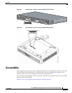
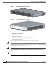
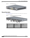
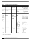
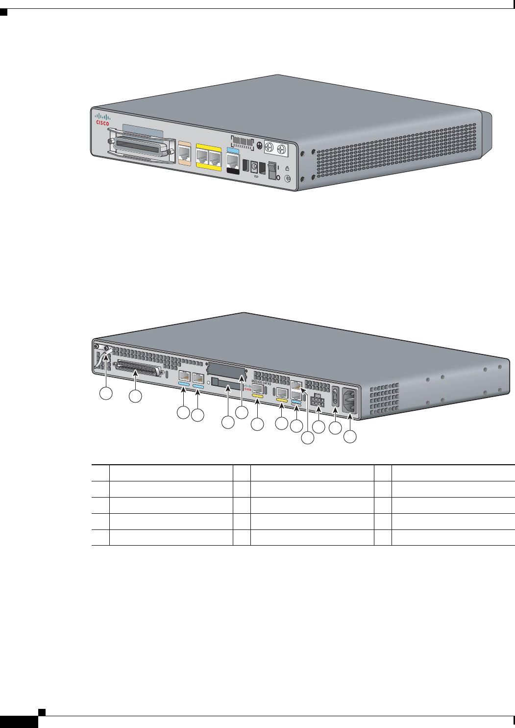
Figure 1-8 Cisco IAD2435-8FXS Chassis
Physical Description
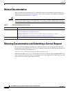
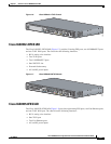
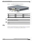
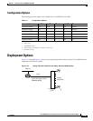
Figure 1-9 and Figure 1-10 show the function options of the two IAD243x chassis. All interface slots
are on the back of the chassis.
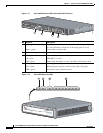
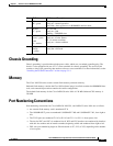
Figure 1-9 Cisco IAD2430 Series IAD Back Panel Function Options
231873
IAD2435-8FXS
12V
D
C
SA
CONSOLE
AU
X
FastEthernet
WAN
0
/1
0
/0
T1/E
1
F
X
S
1 Chassis ground connection 2 RJ-21 connector 3 T1/E1 port 1
4 T1/E1 port 0 5 Flash memory slot 6 WIC/VIC slot
7 10/100BASE-T port 1 8 10/100BASE-T port 0 9 AUX port
10 Console port 11 DC power input
1
1. This is not a redundant failover power supply connection. You must use either DC or AC.
12 On/off switch
13 AC power input
88828
2
1
3
4
7
6
5
8
9
10
11
12
13