


3-15
Cisco IAD2430 Series Integrated Access Devices Hardware Installation Guide
OL-4234-06
Chapter 3 Installing Cisco IAD2430 Series IADs
Installing the Ground Connection
Warning
The importance of proper grounding cannot be overemphasized. It will minimize the potential for
damage to your system and maximize safety at the system site. We recommend you consult a licensed
electrician or your local electric utility company if you have any questions.
Statement 269
Warning
A ground wire must always be a single piece of wire. Never splice two wires together for a ground.
Corrosion and weathering can lead to a poor connection at the splice, making the ground ineffective
and dangerous.
Statement 270
Warning
Use copper conductors only.
Statement 1025
Warning
Installation of the equipment must comply with local and national electrical codes.
Statement 1074
You must connect the chassis to a reliable earth ground; the ground wire must be installed in accordance
with local electrical safety standards.
• For NEBS-compliant grounding, use size AWG 6 (13 mm
2
) wire and the ground lug provided in the
accessory kit.
• For NEC-compliant grounding, use size AWG 14 (2 mm
2
) or larger wire and an appropriate
user-supplied ring terminal.
• For EN/IEC 60950-compliant grounding, use size AWG 18 (1 mm
2
) or larger wire and an
appropriate user-supplied ring terminal.
To ground the chassis, follow these steps:
Step 1 Locate a suitable ground location.
Tip Use a multimeter to measure the resistance between various ground locations, such as the following:
• Between the ground of a junction box (outlet) and the ground of a power tap
• Between the ground of a junction box and a metal water pipe
• Between the Cisco IAD chassis and the ground of a power tap
• Between the Cisco IAD chassis and the ground of a junction box
A good ground connection should read between 0.0 and 0.5 ohm.
Step 2 Strip one end of the ground wire to the length required for the ground lug or terminal.
• For the NEBS ground lug—approximately 0.75 inch (20 millimeters)
• For user-provided ring terminal—as required
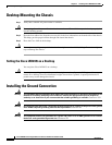
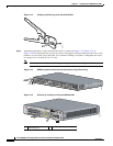
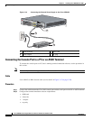
Step 3 Crimp the ground wire to the ground lug or ring terminal, using a crimp tool of the appropriate size. (See
Figure 3-13.)