


3-5
Cisco IAD2430 Series Integrated Access Devices Hardware Installation Guide
OL-4234-06
Chapter 3 Installing Cisco IAD2430 Series IADs
Unpacking and Inspection
–
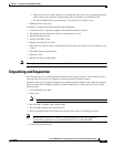
Eight wood screws or other fasteners for installing the chassis on a wall. An additional starter
screw can be used to facilitate wall-mounting (does not include Cisco IAD2435 IAD).
–
For Cisco IAD2435 IAD—two number-six, 3/4-inch (M3.5 x 20-mm) screws.
• ESD-preventive wrist strap
In addition, you might need the following external equipment:
• Console terminal, or personal computer with terminal emulation software
• PC running terminal emulation software for administrative access
• Modem for remote access
• Analog voice RJ-21 cable
• Digital voice RJ-48 T1/E1 cable
• Serial, RJ-48, or RJ-45 cables for connecting WAN interface cards (WICs) or voice interface cards
(VICs)
• CSU/DSU for the serial interfaces
• Ethernet switch
• Modem for remote configuration
Note Serial cables use the Cisco 12-in-1 connector on the WAN connection end.
Unpacking and Inspection
Do not unpack the Cisco IAD2430 series IAD until you are ready to install it. If the installation site is
not ready, keep the chassis in its shipping container to prevent accidental damage.
The IAD, cables, and any optional equipment you ordered might be shipped in more than one container.
When you unpack each shipping container, check the packing list to ensure that you received all the
following items:
• Cisco IAD2430 series IAD
• Power cord
Note Power cords vary, depending upon local requirements.
• RJ-45-to-DB-25 adapter cable (labeled CON)
• RJ-45-to-DB-9 adapter cable (labeled AUX)
• Rack-mounting brackets for 19-inch rack (one pair) with screws for attaching to chassis
Note Rack-mount brackets for 19-inch rack, NEBS grounding kit, and chassis guard for
wall-mounting applications are not included with the Cisco IAD2435-8FXS.
• Grounding lug and fasteners