


2-20
Cisco IE 2000 Switch Hardware Installation Guide
OL-25818-04
Chapter 2 Switch Installation
Connecting to Power
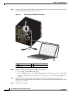
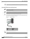
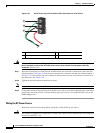
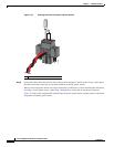
Figure 2-10 AC/DC Power Input Terminal Block Wire Connections to a DC Source
Warning
An exposed wire lead from a DC-input power source can conduct harmful levels of electricity. Be sure
that no exposed portion of the DC-input power source wire extends from the power and relay
connector.
Statement 122
Step 7 Insert the twisted-pair wire leads into the terminal block line and neutral connections. Insert the wire
(labeled number 1 in Figure 2-10) lead into the neutral wire connection and the wire (labeled number 2
in Figure 2-10) lead into the line wire connection. Ensure that only wire with insulation extends from
the connectors. See Figure 2-10.
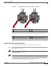
Step 8 Tighten the line and neutral terminal block screws.
Note Torque to 8 in.-lb, not to exceed 10 in-lb.
Step 9 Connect the red wire to the positive pole of the DC power source, and connect the black wire to the return
pole. Ensure that each pole has a current-limiting-type fuse rated to at least 600 VAC/DC (such as the
KLKD Midget fuse).
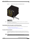
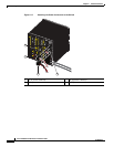
Wiring the DC Power Source
Read these cautions and warnings before wiring the switch the DC power source.
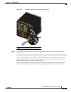
Caution This product is intended to be supplied by a Listed Class 2 power source marked with Class 2 and rated
from 9.6V to 60VDC, 2.1A.
1 Earth ground wire connection 3 Positive DC connection
2 Return wire connection (to DC return)
347819
3
2
1