


2-21
Cisco IE 2000 Switch Hardware Installation Guide
OL-25818-04
Chapter 2 Switch Installation
Connecting to Power
Warning
A readily accessible two-poled disconnect device must be incorporated in the fixed wiring.
Statement 1022
Warning
This product relies on the building’s installation for short-circuit (overcurrent) protection. Ensure that
the protective device is rated not greater than: 3A.
Statement 1005
Warning
Installation of the equipment must comply with local and national electrical codes.
Statement 1074
Warning
Before performing any of the following procedures, ensure that power is removed from the DC circuit.
Statement 1003
Warning
Only trained and qualified personnel should be allowed to install, replace, or service this equipment.
Statement 1030
Caution For wire connections to the power and alarm connectors, you must use UL- and CSA-rated, style 1007
or 1569 twisted-pair copper appliance wiring material (AWM) wire (such as Belden part number 9318).
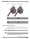
To wire the switch to a DC power source, follow these steps:
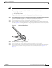
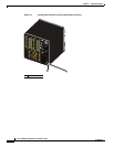
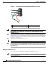
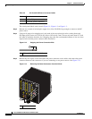
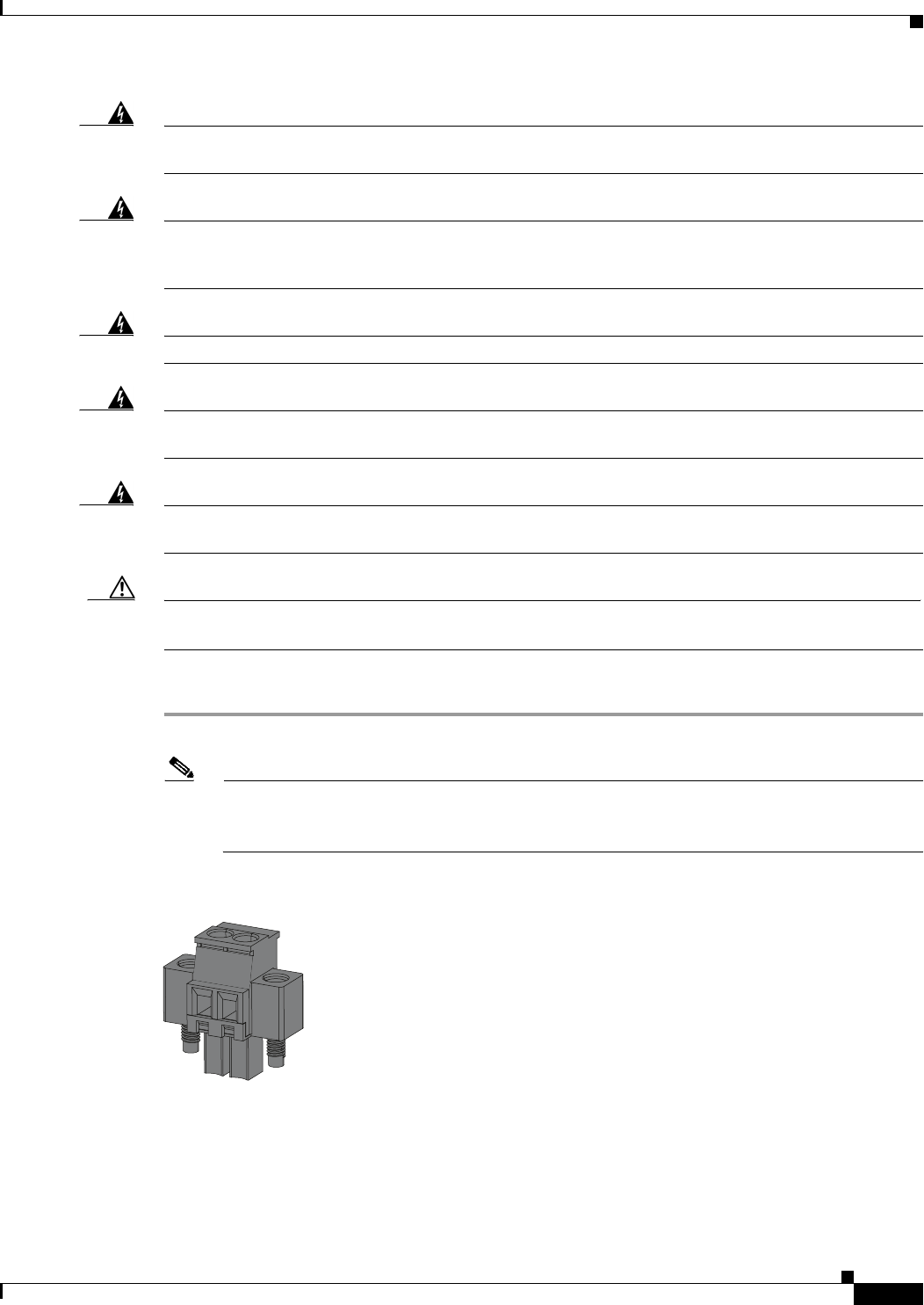
Step 1 Locate the two power connectors on the switch front panel labeled DC-A and DC-B. (See Figure 2-11).
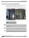
Note On the PoE-capable models of the switch, there is a third DC-input power connector on the
switch front panel labeled PoE. See Connecting Power to the Switch PoE DC-Input (Optional),
page 2-28.
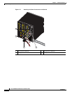
Figure 2-11 Power Connector
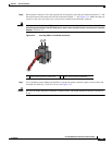
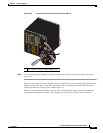
Step 2
Identify the connector positive and return DC power connections. The labels for power connectors DC-A
and DC-B are on the switch panel as displayed in Table 2-2.
331209