


2-23
Cisco IE 2000 Switch Hardware Installation Guide
OL-25818-04
Chapter 2 Switch Installation
Connecting to Power
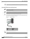
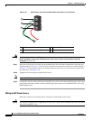
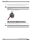
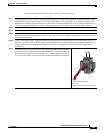
Step 6 On the power connector, insert the exposed part of the positive wire into the connection labeled “+” and
the exposed part of the return wire into the connection labeled “–”. See Figure 2-14. Make sure that you
cannot see any wire lead. Only wire with insulation should extend from the connector.
Warning
An exposed wire lead from a DC-input power source can conduct harmful levels of electricity. Be sure
that no exposed portion of the DC-input power source wire extends from the connector(s) or terminal
block(s).
Statement 122
Figure 2-14 Inserting Wires in the Power Connector
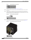
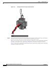
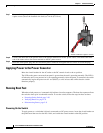
Step 7 Use a ratcheting torque flathead screwdriver to torque the power connector captive screws (above the
installed wire leads) to 2 in-lb (0.23 N-m). See Figure 2-15.
Caution Do not over-torque the power connector’s captive screws. The torque should not exceed 2 in-lb (0.23
N-m).
1 Power source positive connection 2 Power source return connection
332021
1 2