


2-45
Cisco IE 2000 Switch Hardware Installation Guide
OL-25818-04
Chapter 2 Switch Installation
Connecting Destination Ports
Warning
Do not connect or disconnect cables to the ports while power is applied to the switch or any device
on the network because an electrical arc can occur. This could cause an explosion in hazardous
location installations. Be sure that power is removed from the switch and cannot be accidentally be
turned on, or verify that the area is nonhazardous before proceeding.
Statement 1070
Caution Do not remove the rubber plugs from the SFP module port or the rubber caps from the fiber-optic cable
until you are ready to connect the cable. The plugs and caps protect the SFP module ports and cables
from contamination and ambient light.
Before connecting to the SFP module, be sure that you understand the port and cabling guidelines in the
“Preparing for Installation” section on page 2-1. See Appendix B, “Cable and Connectors,” for
information about the LC on the SFP module.
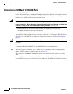
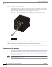
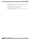
To connect a fiber-optic cable to an SFP module, follow these steps:
Step 1 Remove the rubber plugs from the module port and fiber-optic cable, and store them for future use.
Step 2 Insert one end of the fiber-optic cable into the SFP module port. See Figure 2-30.
Figure 2-30 Connecting to a Fiber-Optic SFP Module Port
1 LC connector
16TC
±12/24/48
0.5-3.0A
331561
1