


2-25
Cisco IE 2000 Switch Hardware Installation Guide
OL-25818-04
Chapter 2 Switch Installation
Connecting to Power
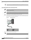
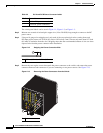
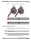
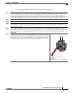
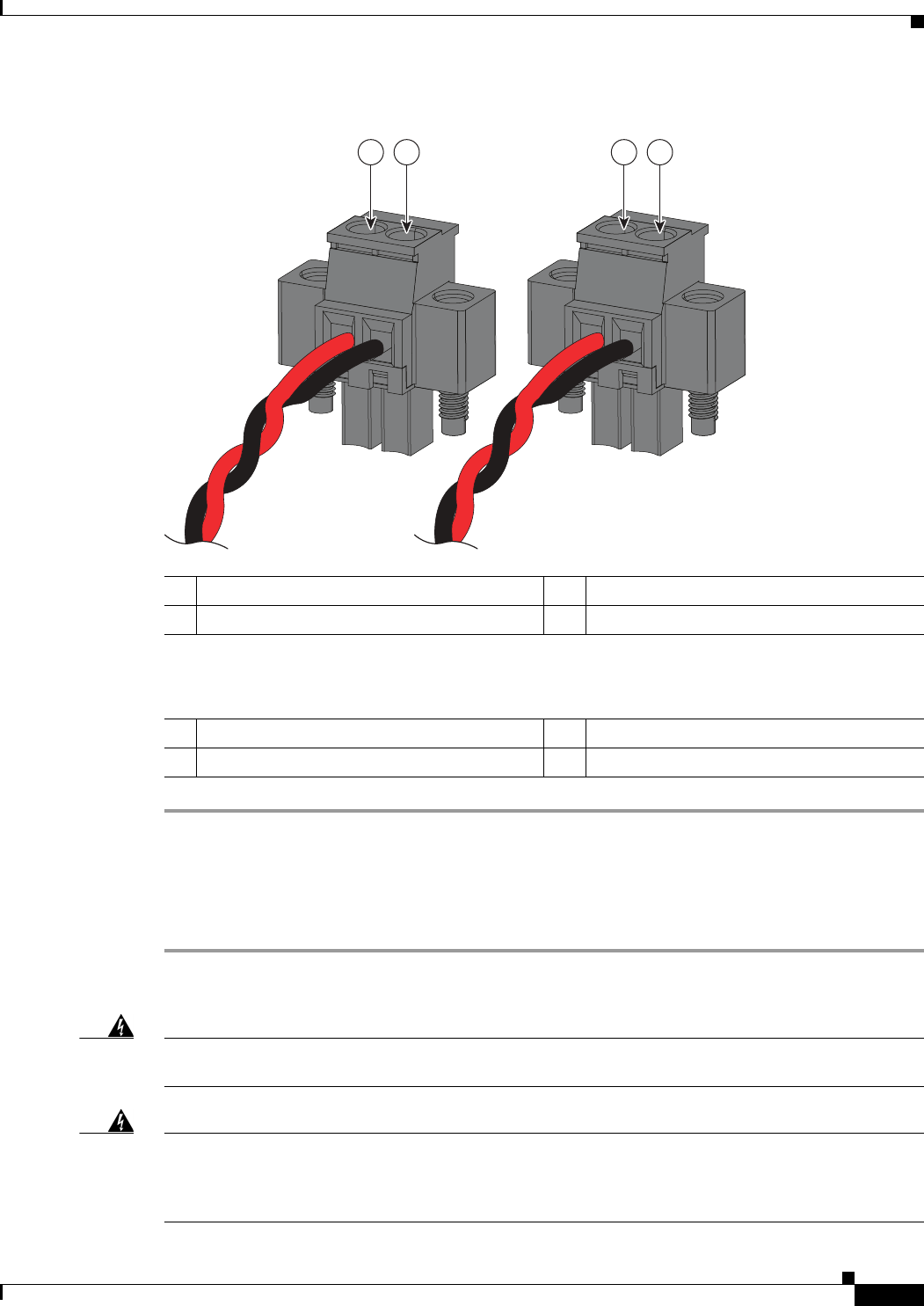
Figure 2-16 Completed DC Power Connections on the Power Connectors
If your power source is –48 VDC, this table describes the your wiring connections for Figure 2-16.
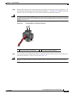
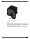
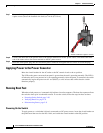
Attaching the Power Connectors to the Switch
To attach the power connectors to the front panel of the switch, follow these steps:
Step 1 Insert one power connector into the DC-A receptacle on the switch front panel, and the other into the
DC-B receptacle. See Figure 2-17.
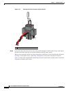
Warning
Failure to securely tighten the captive screws can result in an electrical arc if the connector is
accidentally removed.
Statement 397
Warning
When you connect or disconnect the power and/or alarm connector with power applied, an electrical
arc can occur. This could cause an explosion in hazardous area installations. Be sure that all power
is removed from the switch and any other circuits. Be sure that power cannot be accidentally turned
on or verify that the area is nonhazardous before proceeding.
Statement 1058
1 Power source A positive connection 3 Power source B positive connection
2 Power source A return connection 4 Power source B return connection
332023
1 2 3 4
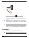
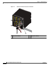
1 Power source A return connection 3 Power source B return connection
2 Power source A –48 VDC connection 4 Power source B –48 VDC connection