


14 Cisco 7000 and Cisco 7507 Chassis Replacement Instructions
Replacing a Rack-Mounted Chassis
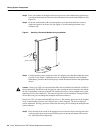
Caution To prevent damage, never attempt to lift or support the front of the chassis with the plastic
front panels. The panels can break away and allow the chassis to drop.
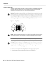
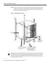
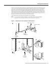
Step 9 To remove the empty chassis from the rack, position one person in the back of the rack to
push the chassis out the front, and position two people in front of the rack to support the
chassis as it is pushed forward out of the rack.
Caution The following step might shift the chassis’ center of gravity to the front of the rack and
may cause the rack or the chassis to tip or fall. Before proceeding, ensure that you have sufficient
assistance to prevent the rack from toppling and the chassis from falling out of the rack.
Step 10 Slowly push the chassis out of the front of the rack while the two assistants in the front of
the rack grasp the chassis along the metal undersides behind the plastic front panels. When
the chassis is clear of the rack, lower it to the floor.
Step 11 Follow the safety guidelines in the section “Lifting the Chassis Safely” on page 8, and
remove the empty chassis from the area.
Replacing the Existing Rack-Mounted Chassis
If sufficient rack space is not available to install both chassis (if you must remove the existing system
from the rack to make room for the replacement chassis), you will have to disconnect all network
interface cables and remove the power supplies before removing the existing system from the rack.
Be sure to label the interface cables to avoid crossing them when you reconnect them to the interface
ports. As you disconnect cables from the interface processors, complete the configuration worksheet
to help you reconnect the cables to the correct ports.
Step 1 Use the configuration worksheet provided at the end of this document or your own method
to label the interface cables and record the port connection for each cable. (For the Cisco
7000, refer to Figure 17, and for the Cisco 7507, refer to Figure 18.)
Step 2 Turn all power supplies OFF.
Note The following warning is for units equipped with DC-input power supplies.
Warning Before performing any of the following procedures, ensure that power is removed from
the DC circuit. To ensure that all power is OFF, locate the circuit breaker on the panel board that
services the DC circuit, switch the circuit breaker to the OFF position, and tape the switch handle of
the circuit breaker in the OFF position. (For translations of this safety warning, refer to the section
“DC Power Disconnection Warning” on page 40.)
Step 3 After reviewing the descriptions in the section “Cable Strain Relief” on page 9, disconnect
all power and network interface cables from the rear of the existing system.