


Cisco 7000 and Cisco 7507 Chassis Replacement Instructions 19
Moving System Components
Failure to use the ejector levers could result in a partial backplane connection and subsequent system
crash. Also, be sure to tighten both the top and bottom captive installation screws on each module to
ensure that it will remain seated properly. When replacing components, work from right to left.
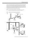
When you remove a processor module, immediately install it in the new chassis and secure it in the
identical slot before removing the next processor module. Before removing processor modules, first
remove the blank board carrier from the corresponding slot in the new chassis so that you can move
the processor module directly into the same slot in the new chassis.
Follow these steps to move the processor modules to the new chassis:
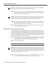
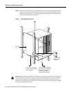
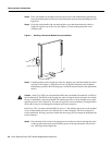
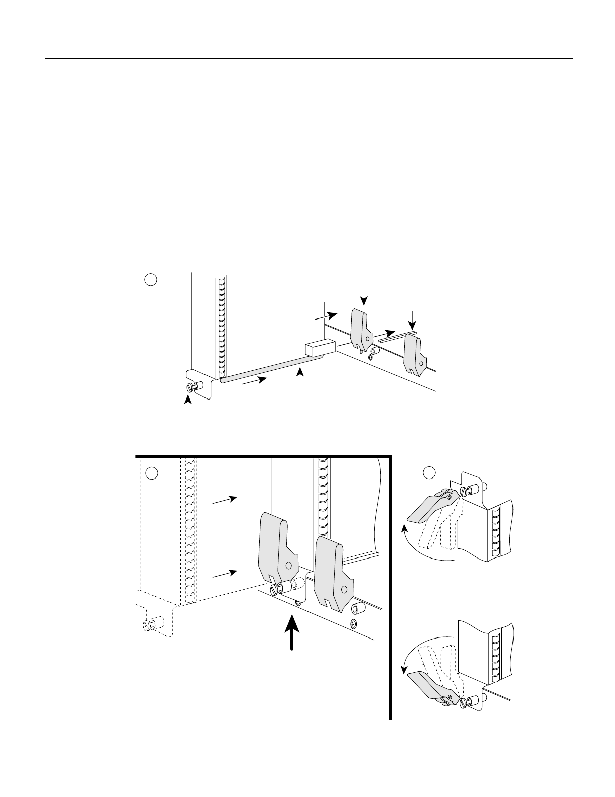
Step 1 Use a screwdriver (Number 2 Phillips or 1/4-inch flat-blade) to loosen the captive
installation screws at the top and bottom of the faceplate. (See Figure 8a).
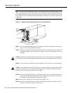
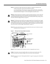
Figure 8 Bottom Ejector Lever and Captive Installation Screw
H1482a
Processor module
slot
a
c
Stop
immediately
on contact
Bottom ejector lever
Captive
installation
screw
Processor
module
carrier guide
b