


20 Cisco 7000 and Cisco 7507 Chassis Replacement Instructions
Moving System Components
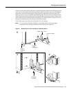
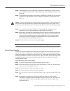
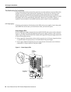
Step 2 Place your thumbs on the upper and lower ejector levers and simultaneously push the top
lever up and the bottom lever down to release the board connector from the backplane. (See
Figure 8c.)
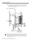
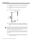
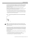
Step 3 Grasp the carrier handle with one hand and place your other hand under the carrier to
support and guide it out of the slot. (See Figure 9.) Avoid touching the board or any
connector pins.
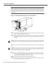
Figure 9 Handling a Processor Module During Installation
Step 4
Carefully pull the carrier straight out of the slot, keeping your other hand under the carrier
to guide it. (See Figure 9.) Keep the carrier at a 90-degree orientation to the backplane.
Immediately proceed to the following step to install the removed board in the replacement
chassis.
Caution In the Cisco 7000, you must install the RP in the slot labeled RP, and the SP (or SSP) in
the slot labeled SP. The RP slot is the far right slot when viewing the chassis from the rear, and the
SP slot is immediately to the left of the RP. The interface processors can be installed in any of the
interface processor slots, labeled 0-4. The slots are keyed for correct installation. Forcing the RP or
SP into the wrong slot can damage the backplane and board connectors.
In the Cisco 7507, you must install the RSP2 in slot 2 or 3. The interface processors can be installed
in any of the interface processor slots, labeled 0 and 1, and 4 through 6. The slots are keyed for
correct installation. Forcing a processor module into the wrong slot can damage the backplane and
board connectors.
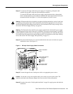
Step 5 Place the back of the carrier in the appropriate slot in the new chassis and align the notch
on the top and bottom of the carrier with the groove in the top and bottom of the chassis
slot. (See Figure 8a and Figure 8b).
H1355a