


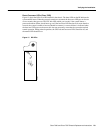

Cisco 7000 and Cisco 7507 Chassis Replacement Instructions 25
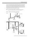
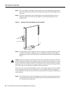
Verifying the Installation
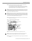
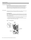
Step 2 After turning on the lower power supply, turn ON the upper power supply (if one is present)
for redundant power. The upper power LED on the front of the chassis will go on.
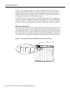
Step 3 While the system initializes, the boot error LED on the RP (or the CPU halt LED on the
RSP2 and RP) goes on for about five seconds or less, then goes out when the boot is
complete. The interface processor LEDs also go on in irregular sequence as the RP (or
RSP2) initializes each one.
Step 4 After the system boots the software and initializes the interface processors (approximately
30 seconds), verify that the RP (or RSP2) LEDs are in the following states:
• Normal LED is on
• CPU halt LED is off (on the RSP2 and RP)
• Boot error LED is off (on the RP)
Step 5 Verify that all of the enabled LEDs on all interface processors (and on the SP or SSP in the
Cisco 7000) are on.
Step 6 Verify that the console terminal displays a script and system banner.
When you have verified all of the conditions in Steps 1 through 6, the replacement procedure is
complete, and you can now resume normal operation.
An error condition exists if no indicators go on at power up or after initialization, or if the boot error
or CPU halt LEDs go on and remain on. If this happens, proceed to the section “Troubleshooting the
Installation” to isolate the problem.