


28 Cisco 7000 and Cisco 7507 Chassis Replacement Instructions
Verifying the Installation
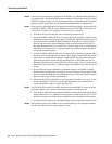
In systems with a single power supply, and in systems with redundant power when both power
supplies are being shut down, the DC fail (or output fail) LED goes on momentarily as the system
ramps down, but goes out when the power supply has completely shut down. In systems with
redundant power and one power supply still active, the DC fail (or output fail) LED on the failed
power supply will remain on (powered by the active supply).
It is unlikely that the power supply will shut down during startup because of an overtemperature
condition; it can, however, shut down if it detects an overvoltage or undervoltage condition during
startup. Refer to the Cisco 7000 Hardware Installation and Maintenance or Cisco 7507 Hardware
Installation and Maintenance publications for descriptions of environmental monitoring functions.
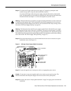
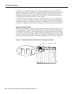
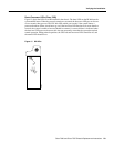
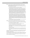
System Front Panel LEDs
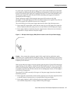
Three system status LEDs on the front of the chassis, shown in Figure 14, indicate the status of the
system and the power supplies. The normal LED (which is controlled by the RP or RSP2) goes on
to indicate that the system is in a normal operating state. The upper power and lower power LEDs
go on to indicate that a power supply is installed in the indicated power supply bay and is providing
power to the system. The chassis front panel upper or lower power LED should go on whenever the
power supply in the corresponding bay is turned on, and the power LED on the power supply is on.
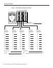
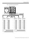
Figure 14 Front Panel LEDs (Cisco 7000 Shown—Identical to Cisco 7507)
UPPER
POWER
LOWER
POWER
NORMAL
Cisco 7000
UPPER
POWER
LOWER
POWER
NORMAL
H1407a