


22 Cisco 7000 and Cisco 7507 Chassis Replacement Instructions
Moving System Components
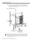
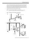
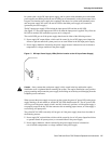
Note Use both hands to handle power supplies. Each weighs 20 pounds. If the power supply resists
when you attempt to pull it out of the bay, the switch is probably not fully in the OFF (O) position,
or the captive installation screw at the top of the supply is not fully loosened. Turn the power switch
fully counterclockwise to OFF (O), and check the captive installation screw, then try removing the
supply again.
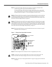
Figure 10 Handling a Power Supply (AC-Input Power Supply Shown)
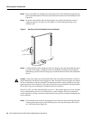
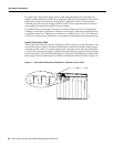
Step 7
Fill the lower power supply bay first. Insert the rear of the power supply into the bay and
align it so that it will go straight into the bay.
Step 8 Push the power supply all the way into the bay. Do not use unnecessary force; firmly push
the supply back into the bay until the power supply front panel is flush against the chassis
rear panel.
Caution When inserting a power supply into the bay, do not use unnecessary force; slamming the
power supply into the bay can damage the connectors on the rear of the supply and inside the chassis.
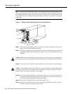
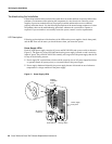
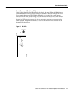
Step 9 Use a screwdriver to tighten the captive installation screw on the top of the power supply.
Caution Always tighten the captive installation screw at the top of the power supply before turning
on the power switch. This screw prevents the power supply from shifting away from the internal
connector and provides proper grounding for the supply.
Step 10 If you are removing or installing a second power supply, use a screwdriver to remove the
cover plate from the upper power supply bay. Store the removed cover plate and replace it
whenever the system is operating with one power supply.
Step 11 Repeat Steps 2 through 9 for the second power supply, if any.
Step 12 On each power supply in the new chassis, push the cable retention clip down, away from
the power cord port, and plug in the power cord.
I
0
DC FAIL
AC POWER
H1356a
Captive
installation
screw