


Cisco 7000 and Cisco 7507 Chassis Replacement Instructions 31
Verifying the Installation
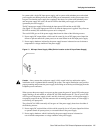
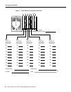
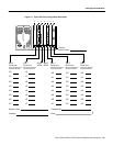
Interface Processor, SP, and SSP LEDs
The SP or SSP (on the Cisco 7000) and all interface processors contain an enabled LED. When on,
this LED indicates that the SP or interface processor is operational and that it is powered up. It does
not necessarily mean that the interface ports on the interface processors are functional or enabled.
When the boot sequence is complete, all of the enabled LEDs (on the SP and all interface processors)
should go on. If any do not go on, one of the following errors is indicated:
• The interface processor or SP is not installed correctly (it is not fully seated in the backplane
connector).
• The SP or interface processor has failed.
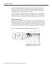
System Startup Sequence
By checking the state of the LEDs, you can determine when and where the system failed in the
startup sequence. The functions of the chassis front panel LEDs are duplicated on the RP (or RSP2)
and the power supplies. Because you turn on the system power with the power supply switches, it is
easiest to observe the startup behavior from the rear of the chassis.
Most often, problems you encounter while replacing the components in a new chassis will be caused
by power supplies or processor modules that are not properly installed and, therefore, are not
connected properly inside the chassis. Use the following descriptions of the normal startup sequence
to isolate the problem, then use the troubleshooting procedures wherever the system fails to operate
as expected.
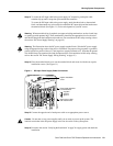
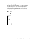
When you start up the system by turning on the power supply switches (lower power supply first,
upper power supply second) you should observe the following:
Step 1 When you turn the lower power supply ON, the power LED on the lower power supply
should go on, and the DC fail (or output fail) LED should remain off.
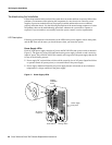
• If the power supply switch resists, the power supply is probably not fully inserted into
the bay. Turn the power switch OFF (fully counterclockwise to O), pull the power
supply out of the bay about two inches, then push the power supply firmly back into the
slot. Do not slam the supply into the slot; doing so can damage the connectors on the
supply and the backplane. Tighten the captive installation screw before proceeding.
• If the power LED goes on, the power source is good, and the power supply is functional.
• If the DC fail (or output fail) LED goes on, or if the power LED does not go on, suspect
the power supply or the power source. Try to power up the system with the upper power
supply if one is present.
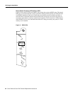
Step 2 When you turn the upper power supply ON, the power LED on the upper power supply
should go on, and the DC fail (or output fail) LED should remain off.
• If the power LED goes on, the power source is good, and the power supply is functional.
• If the DC fail (or output fail) LED goes on, or if the power LED does not go on, suspect
the power supply or the power source. If the lower power supply is functioning properly,
continue monitoring the startup sequence.
• If the LEDs on one or both power supplies fail to go on as expected, suspect a power
supply or input power failure. Before contacting a service representative, refer to the
Cisco 7000 Hardware Installation and Maintenance or Cisco 7507 Hardware
Installation and Maintenance publications for power subsystem troubleshooting
procedures.